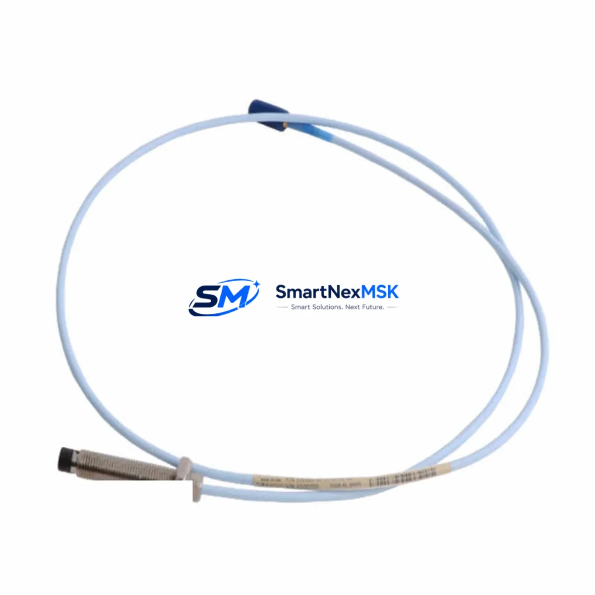
Bently Nevada 330103-11-19-10-02-00 3300 XL Retrofit-Ready Proximity Probe
The Bently Nevada 330103-11-19-10-02-00 is an 8mm eddy-current proximity probe engineered for the 3300 XL vibration monitoring platform. As legacy rotating machinery protection systems age out of OEM support cycles, this probe serves as a direct retrofit replacement for discontinued 3300 Series and early 3300 XL field installations. Whether you are upgrading a turbine protection panel, replacing a failed shaft-sensing probe on a compressor train, or restoring a mothballed monitoring rack, the 330103-11-19-10-02-00 delivers the dimensional and electrical compatibility required for a low-risk, minimum-downtime swap.
This probe is designed to interface directly with the Bently Nevada 3300 XL 8mm Extension Cable (330130 series) and the 3300 XL Proximitor Sensor (330180 series), preserving the original signal chain without requiring recalibration of the Proximitor output or modification of the DCS input card scaling. The probe tip geometry, thread size, and cable connector are identical to the original factory specification, allowing technicians to reuse existing probe holders, lock nuts, and conduit fittings already installed in the machinery casing.
Upgrade Compatibility Table
| Parameter | Detail |
|---|---|
| SKU / Part Number | 330103-11-19-10-02-00 |
| Brand | Bently Nevada |
| Series | 3300 XL 8mm Proximity Transducer System |
| Probe Diameter | 8mm |
| Probe Length | 11mm tip, 19mm body (per SKU suffix) |
| Cable Length | 2.0m integral cable (02 suffix) |
| Connector Type | Standard 3300 XL coaxial, compatible with 330130 extension cables |
| Proximitor Compatibility | 330180 series Proximitor Sensor |
| Gap Voltage Range | -10 VDC nominal at 1.0mm gap (standard 3300 XL calibration) |
| Target Material | AISI 4140 steel or equivalent ferromagnetic shaft material |
| Installation Thread | M10 x 1.0 (standard 3300 XL probe holder) |
| Replaces / Supersedes | 3300 Series 8mm probes; early 3300 XL field variants |
| DCS / Safety System Input | Compatible with existing 4–20 mA or voltage input cards scaled for 3300 XL |
| Communication Protocol | Analog (passive eddy-current); no firmware required |
| Commissioning Requirement | Gap voltage verification at target shaft; no Proximitor re-ranging required |
| Warranty | 12 Months from date of shipment |
Retrofit Planning for Existing Automation Systems
A successful retrofit of the 330103-11-19-10-02-00 into an operating plant begins well before the maintenance window opens. The first step is a power budget review of the existing 3300 XL Proximitor Sensor (330180-91-00 or equivalent). The Proximitor draws its excitation from the monitor rack’s internal power supply — typically a Bently Nevada 3500/42M Proximitor I/O Module or a legacy 3300/16 monitor card. Confirm that the rack power supply (often a 3500/15 Power Supply module) can sustain the probe’s operating current without voltage droop, particularly if additional I/O cards have been added to the chassis since the original installation.
Terminal wiring is the next critical checkpoint. The 330103-11-19-10-02-00 uses a coaxial signal path: the center conductor carries the high-frequency oscillator signal from the Proximitor, and the shield is the return. When connecting to a 3500 Series monitor rack via a 3500/42M or 3500/44M I/O module, verify that the field terminal block assignments match the original loop drawing. If the plant has migrated from a 3300/16 single-channel monitor to a 3500/42M dual-channel card, the terminal numbering will differ and the loop drawing must be updated before energizing.
Backplane and rack interface compatibility is straightforward for 3500 Series chassis: the 330103-11-19-10-02-00 connects to the field side of the I/O module, not the backplane directly. However, if the existing rack is a legacy 3300 Series chassis, confirm that the rack’s internal bus voltage (-24 VDC) is within tolerance, as degraded power supplies in aging racks can cause the Proximitor to output a shifted gap voltage that mimics a probe fault.
Module addressing is not applicable to this analog probe — there is no node address or device ID to configure. However, if the plant’s condition monitoring system uses a System 1 Evolution software platform connected to the 3500 rack via a 3500/92 Communication Gateway Module, verify that the channel tag assignments in System 1 still map correctly to the physical probe location after replacement. A mismatch between the software channel tag and the physical probe position is a common source of post-retrofit alarm confusion.
Program compatibility in the associated safety or control system (typically a Triconex TRICON, Emerson DeltaV SIS, or Yokogawa ProSafe-RS) should be reviewed to confirm that the vibration trip setpoints, time delays, and voting logic remain valid for the replacement probe’s sensitivity. If the original probe was a non-standard calibration variant, the replacement 330103-11-19-10-02-00 (standard 3300 XL calibration) may produce a slightly different gap voltage at the same physical gap, requiring a setpoint review before returning the machine to service.
HMI screen updates are often overlooked during probe replacements. If the plant uses a Wonderware InTouch, Ignition SCADA, or Emerson DeltaV DCS operator station, confirm that the vibration trend displays and alarm banners reference the correct engineering unit scaling (mils peak-to-peak or µm peak-to-peak) consistent with the 3300 XL system’s output. No hardware change is needed, but a functional test of the HMI alarm response is recommended before closing the work order.
Communication link integrity between the 3500 rack and the plant DCS should be verified post-installation. If the rack communicates via a 3500/92 Modbus TCP or OPC gateway, a live data poll from the DCS historian (such as OSIsoft PI or Aspen InfoPlus.21) will confirm that the replacement probe’s gap voltage and vibration amplitude values are being received and archived correctly.
Field commissioning follows a standard gap-setting procedure: with the machine at rest, adjust the probe tip-to-shaft gap to achieve the nominal -10 VDC Proximitor output (approximately 1.0mm for standard 3300 XL calibration). Use a calibrated digital voltmeter at the Proximitor output terminals. Lock the probe in position with the probe holder lock nut, apply thread-locking compound per the plant’s maintenance standard, and record the as-left gap voltage on the work order. A final functional test — simulating a high-vibration condition by tapping the shaft or using a calibration simulator — confirms that the monitor rack, DCS, and safety system all respond correctly before the machine is returned to service.
Downtime Control During System Migration
Minimizing unplanned downtime during a probe replacement on a running production line requires a structured pre-outage preparation protocol. Before the maintenance window, stage all replacement components at the work site: the 330103-11-19-10-02-00 probe, the appropriate 330130 series extension cable (if the existing cable is also being replaced), a calibrated gap-setting tool, and a digital voltmeter. Pre-cut and label all field wiring to match the existing loop drawing so that reconnection is a direct pin-for-pin swap.
To protect the original program logic in the associated safety system, place the affected vibration channel in bypass mode (per the plant’s Management of Change procedure) before disconnecting the probe. This prevents a spurious trip signal from propagating to the ESD system during the physical swap. Document the bypass activation time and assign a dedicated watch to monitor the machine’s mechanical condition by alternative means (portable vibration analyzer or operator rounds) for the duration of the bypass.
The physical probe swap on a standard 3300 XL installation typically takes 15–30 minutes for an experienced instrumentation technician: disconnect the coaxial cable at the Proximitor, unthread the probe from the holder, install the replacement 330103-11-19-10-02-00, set the gap voltage, reconnect the cable, and verify the Proximitor output. The monitor rack does not need to be powered down for a probe replacement — the Proximitor continues to operate normally with the probe disconnected, outputting a fault voltage that the monitor interprets as a probe fault alarm rather than a trip condition.
Once the replacement probe is installed and the gap voltage is confirmed, remove the bypass, verify that the monitor rack clears the probe fault alarm, and confirm that the vibration reading is within the expected baseline range for the machine at rest. A short run-up test (if operationally feasible) provides the highest confidence that the replacement probe is performing correctly before the machine is returned to full load.
Retrofit Support FAQ
Q1: Is the 330103-11-19-10-02-00 a direct drop-in replacement for my existing 3300 XL 8mm probe?
Yes. The 330103-11-19-10-02-00 is dimensionally and electrically identical to the standard 3300 XL 8mm proximity probe specification. It uses the same M10 x 1.0 thread, the same coaxial connector for the 330130 extension cable, and the same standard 3300 XL calibration curve. No Proximitor re-ranging or monitor card reconfiguration is required for a like-for-like replacement.
Q2: Do I need to recalibrate the 330180 Proximitor Sensor after installing the replacement probe?
Not for a standard replacement. The 330103-11-19-10-02-00 is factory-calibrated to the standard 3300 XL sensitivity curve. You only need to set the physical gap to achieve the nominal -10 VDC output at the target gap distance. If your existing Proximitor was configured for a non-standard calibration (e.g., for a non-ferromagnetic target material), contact your instrumentation engineer before proceeding.
Q3: What wiring checks should I perform before energizing the replacement probe?
Verify continuity and insulation resistance of the coaxial cable from the probe connector to the Proximitor input terminals. Confirm that the shield is grounded at one end only (typically at the Proximitor or the monitor rack terminal block) to avoid ground loops. Check that the terminal block assignments match the original loop drawing, particularly if the rack has been modified since the original installation.
Q4: What does the 12-month warranty cover, and what is the shipping lead time?
The 12-month warranty covers manufacturing defects and electrical performance failures under normal operating conditions. It does not cover damage caused by incorrect installation, overvoltage, or mechanical impact. Units are shipped from verified stock with pre-shipment functional testing. Standard lead time is 3–7 business days for in-stock units; expedited shipping is available on request. Contact sales@smartnexmsk.com or +86 18259474341 for availability confirmation before placing your order.
© 2026 SMARTNEXMSK. All rights reserved.
Original Source: https://smartnexmsk.com
Contact: sales@smartnexmsk.com | +86 18259474341


