Bently Nevada 330104-00-02-05-02-00 Retrofit-Ready Proximity Transducer for 3300 XL Control Systems
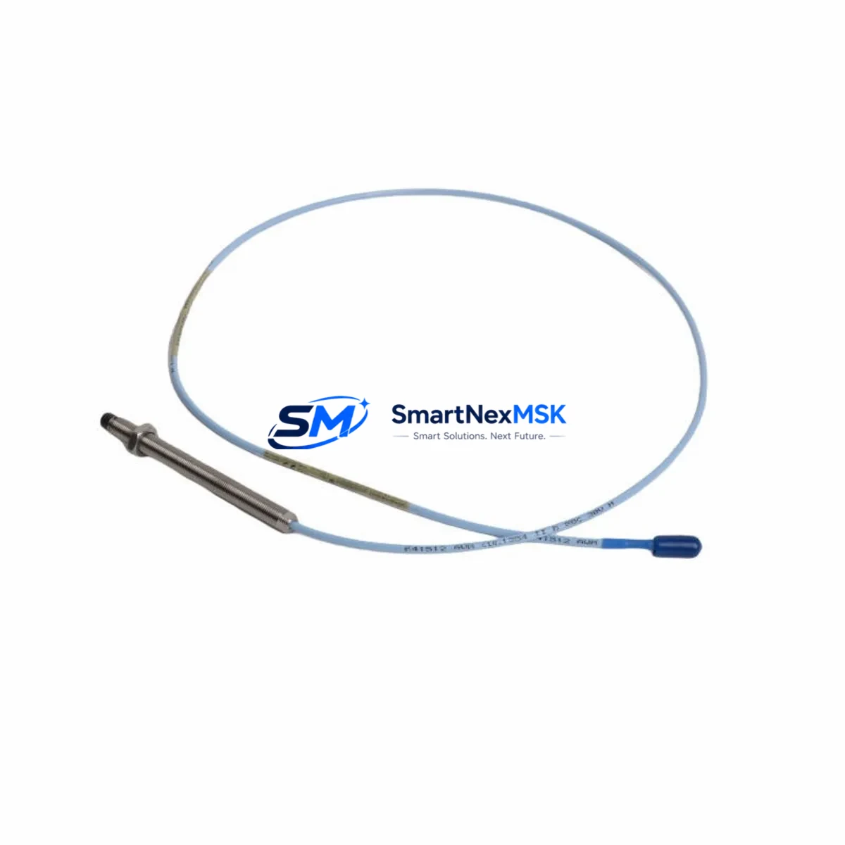
The Bently Nevada 330104-00-02-05-02-00 is a 5mm proximity transducer engineered for seamless integration into existing 3300 XL Series vibration monitoring systems. As legacy Bently Nevada transducer assemblies reach end-of-life or become increasingly difficult to source, the 330104-00-02-05-02-00 provides a verified drop-in replacement path that preserves original wiring topology, signal conditioning compatibility, and system calibration integrity — minimizing retrofit risk and unplanned downtime across rotating machinery protection applications.
This transducer is widely deployed in turbine supervisory instrumentation, compressor train monitoring, and pump protection panels where the 3300 XL rack infrastructure remains in service. It is fully compatible with the 3300 XL proximitor/seismic monitor and interfaces directly with the 3300/16 and 3300/20 monitor modules without requiring firmware changes or signal re-scaling. Engineers migrating from earlier 7200 Series transducer assemblies will find the 330104-00-02-05-02-00 a reliable upgrade candidate, provided terminal block wiring and cable extension lengths are verified against the original loop documentation.
Upgrade Compatibility Table
| Parameter | 330104-00-02-05-02-00 | Notes / Retrofit Guidance |
|---|---|---|
| Transducer Type | 5mm Proximity (Eddy Current) | Compatible with 3300 XL proximitor housings |
| Output Range | −18 VDC nominal | Verify power supply rail on 3300/05 power module |
| Cable Length | 5m (extension cable required for longer runs) | Use Bently Nevada 330130 extension cable for gap adjustment |
| Connector Interface | Standard BNC / coaxial | Confirm mating connector on existing field junction box |
| Mounting Thread | M8 × 1.0 | Check bracket bore; re-tap if replacing 7200 Series units |
| Communication Compatibility | Analog (4–20 mA via monitor) | No protocol change required for 3300 XL rack |
| Monitor Module Compatibility | 3300/16, 3300/20, 3300/25 | Confirm slot addressing in System 1 configuration |
| Installation Requirement | Gap setting: 1.0–1.5 mm nominal | Use gap tool; verify with oscilloscope before energizing |
| Commissioning Focus | Bias voltage, gap, and sensitivity check | Document as-found / as-left in maintenance record |
| Warranty | 12 Months | Covered from date of shipment; includes DOA replacement |
Retrofit Planning for Existing Automation Systems
Successful integration of the 330104-00-02-05-02-00 into a live plant environment requires a structured pre-outage review. Begin by auditing the existing 3300 XL rack configuration — confirm the number of occupied monitor slots, the firmware revision of each 3300/16 or 3300/20 monitor module, and the current System 1 software version managing alarm setpoints and trend data. If the rack also houses a 3300/55 keyphasor module, verify that the new transducer’s phase reference relationship is preserved during the swap.
Terminal wiring should be mapped against the original loop drawing before any field disconnection. The 330104-00-02-05-02-00 uses the same three-conductor shielded cable convention as predecessor assemblies, but shield grounding practice at the junction box must be confirmed — improper grounding is a common source of noise injection that can trigger spurious alarms on the 3300/20 monitor. Where cable runs exceed the standard 5m transducer length, a Bently Nevada 330130 Series extension cable must be inserted and the total loop resistance recalculated to ensure the proximitor output remains within the monitor’s input window.
For facilities running a Bently Nevada 3500 Series rack in parallel with legacy 3300 XL infrastructure, the 330104-00-02-05-02-00 can serve as an interim transducer during a phased migration. In this scenario, the 3500/42M monitor module may be pre-configured in the new rack while the 3300 XL rack remains online, allowing a hot-cutover with minimal process interruption. The 3500/22M transient data interface should be configured to accept the same channel mapping as the outgoing 3300 XL slot to preserve historian continuity in System 1.
I/O mapping in the DCS or safety system must also be reviewed. If the vibration signal is hardwired to a Yokogawa CENTUM VP or Emerson DeltaV I/O card, confirm that the analog input range and engineering unit scaling match the new transducer’s sensitivity specification (200 mV/mil or 7.87 V/mm). Any HMI faceplate in the control room that displays vibration trend or alarm status should be validated against the updated tag database before the outage window closes. Where the plant uses a Modbus RTU or HART gateway to aggregate vibration data, the gateway’s channel configuration file must be updated to reflect the new transducer’s calibration constants.
Downtime Control During System Migration
Minimizing production impact during a proximity transducer replacement requires pre-staging all materials and completing as much bench work as possible before the maintenance window opens. The 330104-00-02-05-02-00 should be bench-tested prior to installation: connect it to a spare 3300 XL proximitor, apply the nominal −24 VDC supply, and verify the output voltage at the specified air gap using a calibrated target disk. Record the bias voltage and sensitivity as a baseline for post-installation comparison.
On the day of the outage, follow a defined sequence: isolate the monitor channel in bypass mode within System 1 to suppress spurious trip signals, disconnect the field cable at the junction box, remove the old transducer, install the 330104-00-02-05-02-00, set the gap, reconnect the cable, and restore the monitor channel from bypass. This sequence typically requires 45–90 minutes per measurement point when performed by a qualified instrumentation technician. Where multiple transducers are being replaced in the same outage, parallel work teams can address separate measurement planes simultaneously to compress the total outage window.
Original program logic in the safety system or DCS should not require modification if the replacement transducer maintains the same sensitivity and output range. However, if the plant’s overspeed or high-vibration trip logic references a specific channel gain factor, that parameter should be confirmed in the System 1 configuration before the monitor is returned to service. Retaining a backup of the System 1 database and the 3300 XL rack configuration file before any hardware change is a non-negotiable step in a controlled retrofit procedure.
Retrofit Support FAQ
Q1: Is the 330104-00-02-05-02-00 a direct drop-in replacement for earlier Bently Nevada 330104 variants?
A: The 330104-00-02-05-02-00 is dimensionally and electrically compatible with other 330104 Series variants in most 3300 XL applications. However, the suffix codes encode cable length, connector type, and temperature rating — confirm each suffix position against your existing loop documentation before ordering to ensure a true drop-in fit without field modification.
Q2: What commissioning steps are required after installation?
A: After mechanical installation, set the transducer gap to the manufacturer’s nominal specification (typically 1.0–1.5 mm for a 5mm probe), verify the bias voltage at the proximitor output terminal, and perform a slow-roll check to confirm the dynamic signal is clean and within the monitor’s alarm window. Document as-found and as-left readings in the maintenance management system before returning the channel to service.
Q3: Can this transducer be used with a Bently Nevada 3500 Series rack?
A: Yes, with configuration. The 330104-00-02-05-02-00 is compatible with the 3500/42M velocity and acceleration monitor when used with the appropriate proximitor. Confirm the 3500 rack’s channel configuration in System 1 matches the transducer’s sensitivity and gap range, and update the I/O module’s scaling accordingly.
Q4: What does the 12-month warranty cover?
A: The 12-month warranty covers manufacturing defects and functional failures under normal operating conditions from the date of shipment. Dead-on-arrival (DOA) units are replaced at no charge. The warranty does not cover damage resulting from incorrect installation, overvoltage, or mechanical impact. All units undergo functional testing prior to shipment.
© 2026 SMARTNEXMSK. All rights reserved.
Original Source: https://smartnexmsk.com
Contact: sales@smartnexmsk.com | +86 18259474341


