Bently Nevada 330104-00-02-90-02-00 Spare for 3300 XL Automation: Precision Spare Parts for Downtime Recovery
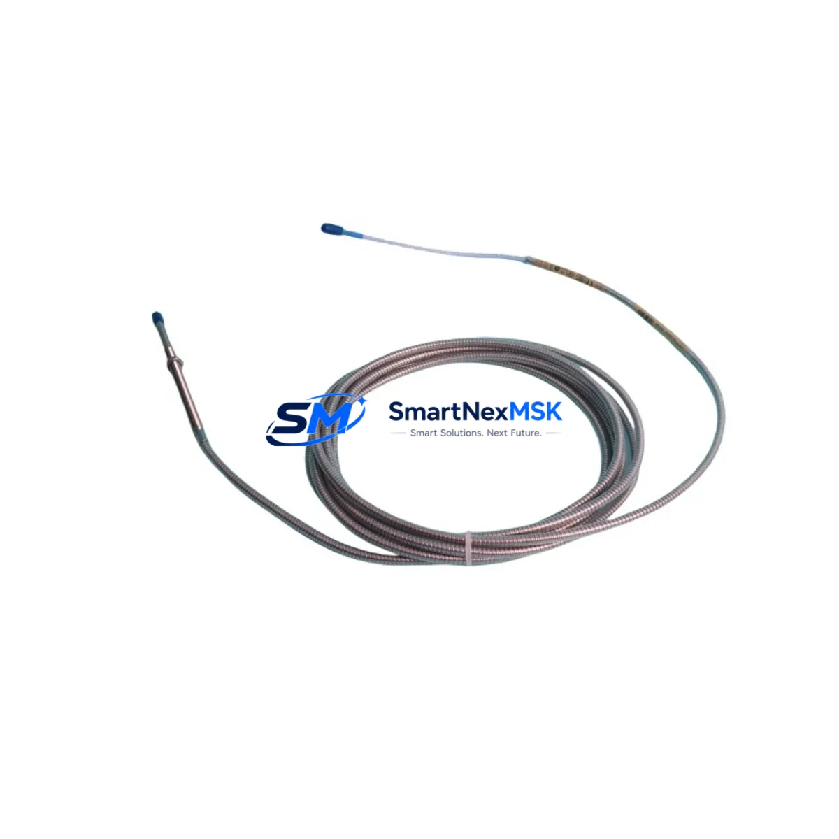
The Bently Nevada 330104-00-02-90-02-00 is an 8mm Eddy Current Proximity Probe engineered for the 3300 XL Series continuous machinery protection system. As a maintenance-ready original spare, this probe delivers the measurement accuracy and signal stability required for vibration monitoring on rotating equipment including turbines, compressors, pumps, and motors in critical industrial environments. Sourced from verified supply channels, each unit undergoes pre-shipment functional testing and ships with a 12-month warranty, ensuring your maintenance team can restore system integrity with confidence.
For maintenance engineers managing aging 3300 XL installations, the 330104-00-02-90-02-00 represents a direct, specification-matched replacement that eliminates the compatibility risk associated with non-original substitutes. Its 8mm tip diameter, standard 5-metre extension cable compatibility, and -24 VDC driver voltage align precisely with the 3300 XL system architecture, allowing rapid field swap-out without recalibration of the monitoring rack.
Spare Maintenance Table
| Parameter | Specification |
|---|---|
| Part Number | 330104-00-02-90-02-00 |
| Brand | Bently Nevada |
| Series | 3300 XL |
| Type | 8mm Eddy Current Proximity Probe |
| Tip Diameter | 8 mm |
| Cable Length | 2.0 m (probe cable) |
| Driver Voltage | -24 VDC (nominal) |
| Output Sensitivity | 7.87 V/mm (200 mV/mil) |
| Linear Range | 0.25 – 2.54 mm (10 – 100 mil) |
| Temperature Range | -35°C to +121°C |
| Compatibility | 3300 XL 8mm Proximity Transducer System |
| Connector Type | Standard BNC / coaxial |
| Installation | Threaded mount, M10 x 1 mm |
| Application | Turbines, compressors, pumps, motors — radial/axial vibration & position |
| Origin | USA |
| Warranty | 12 Months |
| Pre-shipment Test | Functional output & linearity verified |
Maintenance Planning for Continuous Operation
When replacing the 330104-00-02-90-02-00 proximity probe during a planned or emergency shutdown, a thorough inspection of the surrounding measurement chain is essential to prevent repeat failures and ensure the restored system meets API 670 protection standards.
Begin with the 3300 XL Extension Cable (typically the 330130 series, 5-metre standard length). Extension cables are subject to mechanical fatigue at conduit entry points and connector corrosion in humid or chemically aggressive environments. A probe replacement that is paired with a degraded extension cable will produce erratic gap voltage readings and false alarms. Inspect the full cable run and replace if insulation resistance is below specification.
The 3300 XL Proximitor Sensor (driver/oscillator module, e.g. 330180 series) should be bench-tested for output voltage stability at the nominal -24 VDC supply. A failing Proximitor will mask a healthy probe’s signal, leading to misdiagnosis. During the same maintenance window, verify the 3300 XL Monitor Module (such as the 3300/16 or 3300/20 series rack card) for correct gap voltage acceptance range and alarm setpoint integrity.
Power supply quality is a frequent root cause of proximity system instability. Confirm that the 3300 XL Power Supply Module (e.g. 3300/05 or equivalent rack PSU) delivers clean, regulated -24 VDC with ripple within specification. A shared power rail serving multiple monitor cards should be load-tested before returning the machine to service.
For installations where the 3300 XL rack interfaces with a DCS or safety system, inspect the 4–20 mA output isolator or signal conditioner downstream of the monitor. Signal isolation barriers can develop ground loops or drift over time, corrupting the vibration data reaching the control room historian. Similarly, review the terminal block assemblies and field wiring terminations within the control cabinet — loose or oxidised connections at the I/O marshalling panel are a common source of intermittent probe faults that are incorrectly attributed to the probe itself.
If the machine is equipped with a Keyphasor transducer (e.g. 330980 series), verify its gap voltage and signal quality simultaneously, as phase reference data is critical for vector-based vibration analysis and balancing. Finally, check the rack communication interface (e.g. Modbus RTU or System 1 network card) to confirm that the repaired channel is correctly mapped and that alarm states have been reset in the monitoring software before restart.
Site Replacement Workflow
Step 1 — Isolation & Permit: Obtain a work permit and isolate the monitoring channel at the rack. Do not de-energise the entire rack if other channels are protecting running equipment.
Step 2 — Gap Measurement: Record the existing probe gap voltage before removal. This baseline confirms whether the original probe had drifted out of the linear range prior to failure.
Step 3 — Probe Removal: Unthread the 330104-00-02-90-02-00 from its mounting boss using the correct spanner. Inspect the target area on the shaft for surface damage, scoring, or runout that may have caused premature probe wear.
Step 4 — New Probe Installation: Install the replacement probe to the manufacturer’s specified gap (typically 1.0–1.5 mm / 40–60 mil for 8mm probes on steel targets). Torque the locknut to specification. Connect the extension cable and verify continuity.
Step 5 — System Verification: Power the Proximitor and confirm gap voltage is within the linear range on the monitor display. Check that the channel reads correctly in the DCS or System 1 software. Clear any latched alarms.
Step 6 — Return to Service: Document the replacement in the maintenance management system (CMMS), update the spare parts inventory, and log the as-found gap voltage for trend analysis.
This workflow minimises machine downtime, maintains system compatibility, and provides a documented audit trail for reliability engineers and compliance reviews.
Spare Parts Support FAQ
Q1: Is the 330104-00-02-90-02-00 a direct replacement for older 3300 series proximity probes?
The 330104-00-02-90-02-00 is designed for the 3300 XL 8mm transducer system. It is not directly interchangeable with earlier 3300/05 or 7200 series probes without verifying Proximitor compatibility. Always confirm the matched Proximitor part number before installation to ensure the system operates within its calibrated linear range.
Q2: What pre-shipment testing is performed on each unit?
Each 330104-00-02-90-02-00 unit is functionally tested for output voltage linearity, insulation resistance, and connector integrity before dispatch. A test report is available on request. Units are packaged in anti-static, shock-protected packaging to prevent transit damage.
Q3: How should this probe be stored as a long-term spare?
Store in a dry, temperature-controlled environment (10°C–35°C) away from strong magnetic fields and chemical vapours. Keep in original packaging with desiccant. Inspect connector pins and cable insulation annually. Recommended maximum shelf storage before installation is 5 years, after which a functional bench test is advised before deployment.
Q4: What does the 12-month warranty cover?
The 12-month warranty covers manufacturing defects, output signal failure under normal operating conditions, and connector integrity. It does not cover damage resulting from incorrect installation gap, mechanical impact, chemical exposure, or use outside the specified temperature and voltage range. Warranty claims are supported with a return and replacement process — contact our team for RMA procedures.
© 2026 SMARTNEXMSK. All rights reserved.
Original Source: https://smartnexmsk.com
Contact: sales@smartnexmsk.com | +86 18259474341


