Bently Nevada 330104-00-04-10-01-00 Maintenance-Ready Spare for 3300 XL Automation
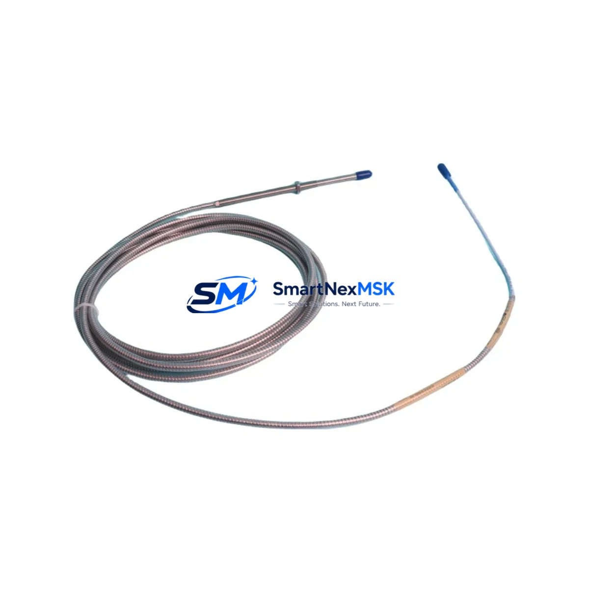
The Bently Nevada 330104-00-04-10-01-00 is an original eddy current proximity transducer engineered for the 3300 XL Series vibration monitoring system. In industrial facilities where rotating machinery — turbines, compressors, pumps, and gearboxes — operates continuously, the reliability of shaft proximity measurement is non-negotiable. An unplanned transducer failure can trigger a full machinery trip, halting production and initiating costly emergency maintenance. Stocking the 330104-00-04-10-01-00 as a certified spare part is a proven strategy for minimizing mean time to repair (MTTR) and maintaining system uptime.
This transducer is designed for radial and axial shaft vibration measurement in compliance with API 670 machinery protection standards. Its 5 mm sensing range, 8 mm probe diameter, and 200 mV/mil (7.87 V/mm) sensitivity make it a precision instrument for critical machine monitoring. Maintenance engineers working on 3300 XL monitoring racks will recognize this part as a direct, plug-compatible replacement for aging or damaged transducers without requiring recalibration of the entire monitoring loop.
Spare Maintenance Table
| Parameter | Specification |
|---|---|
| Part Number | 330104-00-04-10-01-00 |
| Brand | Bently Nevada |
| Series | 3300 XL |
| Type | Eddy Current Proximity Transducer |
| Probe Diameter | 8 mm |
| Sensing Range | 5 mm (0–5 mm linear range) |
| Sensitivity | 200 mV/mil (7.87 V/mm) |
| Supply Voltage | -24 VDC (nominal) |
| Output Signal | DC voltage proportional to gap |
| Cable Length | 1.0 m (extension cable required for full system) |
| Connector Type | 3-pin MIL-spec connector |
| Compatibility | 3300 XL Monitor, 3300/16 Rack, 3500 Series (with adapter) |
| Target Material | Steel, Stainless Steel, Inconel |
| Operating Temperature | -35°C to +120°C |
| Protection Rating | IP67 |
| Application | Radial/Axial Shaft Vibration, Thrust Position, Differential Expansion |
| Compliance | API 670, CE |
| Origin | USA |
| Warranty | 12 Months |
Maintenance Planning for Continuous Operation
When a 330104-00-04-10-01-00 transducer is flagged for replacement during a scheduled outage or emergency shutdown, experienced maintenance engineers know that the transducer itself is rarely the only component requiring attention. A thorough inspection of the entire proximity measurement loop is essential to prevent repeat failures and ensure accurate vibration data after restart.
Begin by inspecting the 330130-080-00-00 extension cable — the interconnect between the probe and the proximitor. Cable insulation degradation, connector corrosion, or mechanical damage from vibration fatigue are common failure modes that can mimic transducer faults. Next, verify the condition of the 330180-X0-05 proximitor/driver (Velomitor or equivalent), which conditions the transducer signal before it reaches the monitor card. A faulty proximitor will produce erratic gap voltage readings even with a new transducer installed.
At the rack level, inspect the 3300/16 monitor card or the relevant 3500/42M proximitor I/O module for signs of overheating, blown fuses, or failed relay outputs. The 3300/20 power supply module should be checked for stable -24 VDC output — voltage sag or ripple will directly affect transducer linearity. If the system uses a 3500/92 communication gateway for Modbus or Ethernet output, verify that the module is correctly synchronized after any rack power cycle.
For facilities running older 3300 Series racks alongside newer 3500 Series infrastructure, confirm that the 3300 XL proximitor and the replacement transducer are matched as a calibrated pair — mixing unmatched probes and proximitors is a leading cause of post-maintenance alarm nuisance trips. Additionally, check the terminal strip and field wiring in the junction box for loose connections, moisture ingress, or ground loops that can introduce noise into the measurement signal.
Where the 330104-00-04-10-01-00 is used for thrust position monitoring, also inspect the 3300/55 thrust position monitor and its associated relay module. Confirm that the OK relay output is functioning correctly and that the danger/alert setpoints have not drifted due to previous manual overrides during emergency operation.
Site Replacement Workflow
Step 1 — Isolation and Lockout: Follow site LOTO procedures. De-energize the monitor rack and confirm zero energy state at the junction box before disconnecting the transducer.
Step 2 — Gap Measurement: Before removing the old transducer, record the installed gap voltage using a calibrated voltmeter. The nominal gap for the 330104-00-04-10-01-00 is typically 1.0–1.5 mm (gap voltage approximately -10 to -12 VDC). This baseline will be used to set the replacement transducer to the same mechanical gap.
Step 3 — Transducer Removal: Unscrew the probe from the bracket using the appropriate spanner. Disconnect the extension cable at the field junction box. Inspect the probe tip for physical damage, pitting, or contamination from shaft contact.
Step 4 — Installation of 330104-00-04-10-01-00: Thread the new transducer into the bracket. Adjust the gap to the recorded baseline value. Tighten the locknut to the specified torque (typically 2–3 Nm for 8 mm probes). Reconnect the extension cable, ensuring the connector is fully seated and the locking ring is engaged.
Step 5 — System Verification: Re-energize the rack. Confirm the OK LED on the proximitor is illuminated. Verify the gap voltage at the monitor card input matches the expected value. Check that vibration readings are within normal baseline range before releasing the machine for restart.
Step 6 — Documentation: Record the replacement in the maintenance management system (CMMS). Log the new transducer serial number, installation date, gap voltage, and technician ID. Update the spare parts inventory to trigger reorder of the consumed 330104-00-04-10-01-00 unit.
Spare Parts Support FAQ
Q1: Is the 330104-00-04-10-01-00 compatible with both 3300 and 3500 Series monitors?
The 330104-00-04-10-01-00 is natively designed for the 3300 XL Series. It can be used with 3500 Series monitors when paired with the appropriate 3500/42M I/O module and a matched 3300 XL proximitor. Always verify the system configuration with your instrumentation engineer before cross-series installation.
Q2: What is the recommended spare parts stocking strategy for this transducer?
For critical rotating machinery applications, a minimum of one spare transducer per monitored machine train is recommended. Facilities with multiple identical machines should maintain a pooled inventory of 2–3 units. Given typical lead times for OEM parts, maintaining a local stock of the 330104-00-04-10-01-00 eliminates procurement delays during unplanned outages.
Q3: How is each unit tested before shipment?
Every 330104-00-04-10-01-00 unit supplied by SMARTNEXMSK undergoes pre-shipment functional verification including gap voltage linearity check, insulation resistance test, and connector integrity inspection. Units are shipped with individual test records and are covered by a 12-month warranty from the date of delivery.
Q4: What is the warranty coverage and return policy?
All units carry a 12-month warranty covering manufacturing defects and functional failure under normal operating conditions. In the event of a warranty claim, SMARTNEXMSK provides rapid replacement to minimize site downtime. Contact our technical team with the unit serial number and failure description to initiate the process.
© 2026 SMARTNEXMSK. All rights reserved.
Original Source: https://smartnexmsk.com
Contact: sales@smartnexmsk.com | +86 18259474341


