Bently Nevada 330104-00-04-50-02-CN Retrofit-Ready Proximity Transducer for 3300 XL Control Systems
The Bently Nevada 330104-00-04-50-02-CN is an 8mm proximity transducer engineered for seamless integration into Bently Nevada 3300 XL vibration monitoring systems. As legacy machinery monitoring infrastructure ages and OEM support for older transducer assemblies becomes increasingly limited, this unit serves as a direct, wiring-compatible retrofit replacement — enabling plant engineers to restore full system functionality without redesigning existing cable runs, terminal blocks, or monitor rack configurations.
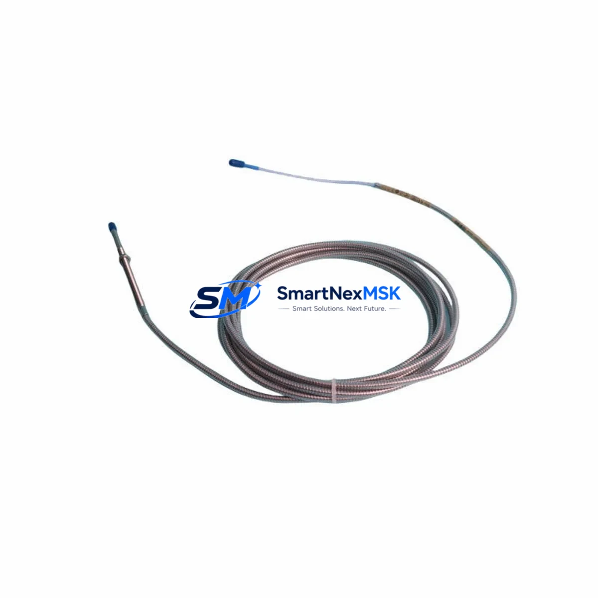
Designed for continuous operation in rotating machinery environments, the 330104-00-04-50-02-CN delivers reliable non-contact displacement measurement across turbines, compressors, pumps, and gearboxes. Its 5-metre extension cable assembly (suffix -50) and standard 2-pin MIL-spec connector (suffix -02) ensure compatibility with the existing 3300 XL proximitor/driver infrastructure, including the 330180 proximitor and 330130 extension cable assemblies commonly found in legacy installations.
When planning a retrofit or spare-parts replenishment for a 3300 XL monitoring loop, engineers must verify several critical parameters before commissioning the replacement unit. Power supply polarity and voltage range (-24 VDC nominal) must match the existing proximitor output. Terminal wiring at the junction box should be inspected for correct shield grounding, particularly where the 330130 extension cable interfaces with the field wiring. The proximitor gap voltage — typically set between -10.0 VDC and -18.0 VDC at the target air gap — must be re-verified after installation using a calibrated voltmeter or the System 1 software interface.
Upgrade Compatibility Table
| Parameter | Detail |
|---|---|
| SKU / Part Number | 330104-00-04-50-02-CN |
| Series Compatibility | Bently Nevada 3300 XL Vibration Monitoring System |
| Transducer Tip Diameter | 8mm |
| Extension Cable Length | 5 metres (suffix -50) |
| Connector Type | 2-pin MIL-spec (suffix -02) |
| Supply Voltage | -24 VDC (nominal) |
| Output Range | -10 VDC to -18 VDC (gap voltage) |
| Compatible Proximitor | Bently Nevada 330180 |
| Compatible Extension Cable | Bently Nevada 330130 |
| Installation Type | Drop-in replacement, no bracket modification required |
| Communication / Protocol | Analogue voltage output; compatible with System 1 software |
| Replacement Recommendation | Direct replacement for discontinued or worn 330104-series transducers |
| Commissioning Requirement | Gap voltage re-verification required post-installation |
| Warranty | 12 months from date of shipment |
Retrofit Planning for Existing Automation Systems
A successful 3300 XL transducer retrofit involves more than a simple part swap. Plant maintenance teams should begin by auditing the full monitoring loop: from the 330104-00-04-50-02-CN probe tip through the 330130 extension cable, into the 330180 proximitor, and finally to the 3300 XL monitor card seated in the rack. Each component in this signal chain must be confirmed operational before the new transducer is commissioned.
In installations where the 3300 XL rack also houses 3300/16 or 3300/20 monitor cards for axial position or differential expansion measurement, the replacement transducer must be verified against the channel configuration stored in the monitor. If the rack includes a 3300/55 keyphasor module, the phase reference signal must remain uninterrupted during the transducer swap to avoid triggering false trip conditions in the control system.
For sites migrating from older 7200 series transducers to the 3300 XL platform, the 330104-00-04-50-02-CN provides a forward-compatible entry point. However, engineers should note that the 7200 series used a different proximitor (3300/05 or 3300/10) and a different gap voltage calibration range. A full recalibration using the System 1 configuration tool is mandatory in cross-series migration scenarios.
Where the control cabinet also contains a Bently Nevada 3500 rack for machinery protection, the transducer signal may be split or re-routed to a 3500/42M position monitor. In such cases, the 3500/42M channel configuration must be updated to reflect the new transducer’s sensitivity (typically 7.87 V/mm for 8mm probes) and the correct OK limit thresholds. The 3500 rack’s I/O module wiring — including the 02-330180-01 field wiring termination — should be inspected for continuity and correct shield termination before the system is returned to service.
Sites operating Bently Nevada System 1 software for condition monitoring should update the asset configuration database to reflect the new transducer serial number and installation date. This ensures that trend data continuity is maintained and that the 12-month warranty period is correctly logged against the replacement unit.
Downtime Control During System Migration
Minimising unplanned downtime during a transducer replacement is a primary concern for any rotating machinery operation. The 330104-00-04-50-02-CN is supplied from stock and can typically be dispatched within 24 hours of order confirmation, reducing lead-time-related downtime risk.
Before initiating the physical swap, the maintenance team should export the current System 1 configuration for the affected machine train. This backup preserves all alarm setpoints, OK limits, and trend history, and allows rapid restoration if the new transducer requires reconfiguration. The 3300 XL monitor card should be placed in bypass mode — not removed from the rack — during the transducer exchange to prevent nuisance trips from propagating to the DCS or safety instrumented system (SIS).
Once the 330104-00-04-50-02-CN is installed and the gap voltage is confirmed within the -10 VDC to -18 VDC acceptance window, the monitor card bypass should be released and the channel observed for a minimum of 15 minutes under normal operating conditions before the machine is returned to full load. Any deviation in the OK relay output or gap voltage trend should be investigated before sign-off.
For critical machinery where continuous monitoring is mandatory, a temporary portable vibration analyser can be connected to the junction box terminals during the swap window to maintain measurement continuity. This approach is particularly recommended for compressor trains or steam turbines where the 3300 XL system feeds a hardwired trip relay in the machinery protection panel.
Retrofit Support FAQ
Q1: Is the 330104-00-04-50-02-CN a direct drop-in replacement for my existing 3300 XL transducer assembly?
Yes. The 330104-00-04-50-02-CN is dimensionally and electrically compatible with all standard 3300 XL 8mm transducer installations using the 330180 proximitor and 330130 extension cable. No bracket modification or cable re-termination is required in most installations. Gap voltage must be re-verified after installation.
Q2: What commissioning steps are required after installation?
After mechanical installation, connect the extension cable to the 330180 proximitor and apply system power. Measure the gap voltage at the proximitor output terminals using a calibrated voltmeter. Adjust the probe-to-target air gap until the gap voltage falls within the -10 VDC to -18 VDC acceptance range (typically -12 VDC at the nominal 1.0mm gap for 8mm probes). Update the System 1 asset configuration with the new transducer serial number and confirm OK relay status before releasing the monitor from bypass.
Q3: Can this transducer be used in a 3500 series rack or only in the 3300 XL?
The 330104-00-04-50-02-CN is optimised for the 3300 XL platform. It can be used with a 3500 rack (e.g., 3500/42M position monitor) provided the channel is reconfigured for the correct transducer sensitivity (7.87 V/mm) and the field wiring termination at the 3500 I/O module is verified. A full channel calibration check is recommended when cross-platform use is intended.
Q4: What warranty coverage is provided, and has the unit been tested before shipment?
All units are function-tested prior to shipment and covered by a 12-month warranty from the date of dispatch. The warranty covers manufacturing defects and electrical performance within the published specification. Units are shipped with a test record confirming gap voltage linearity and OK relay function. For warranty claims or technical support, contact sales@smartnexmsk.com.
© 2026 SMARTNEXMSK. All rights reserved.
Original Source: https://smartnexmsk.com
Contact: sales@smartnexmsk.com | +86 18259474341


