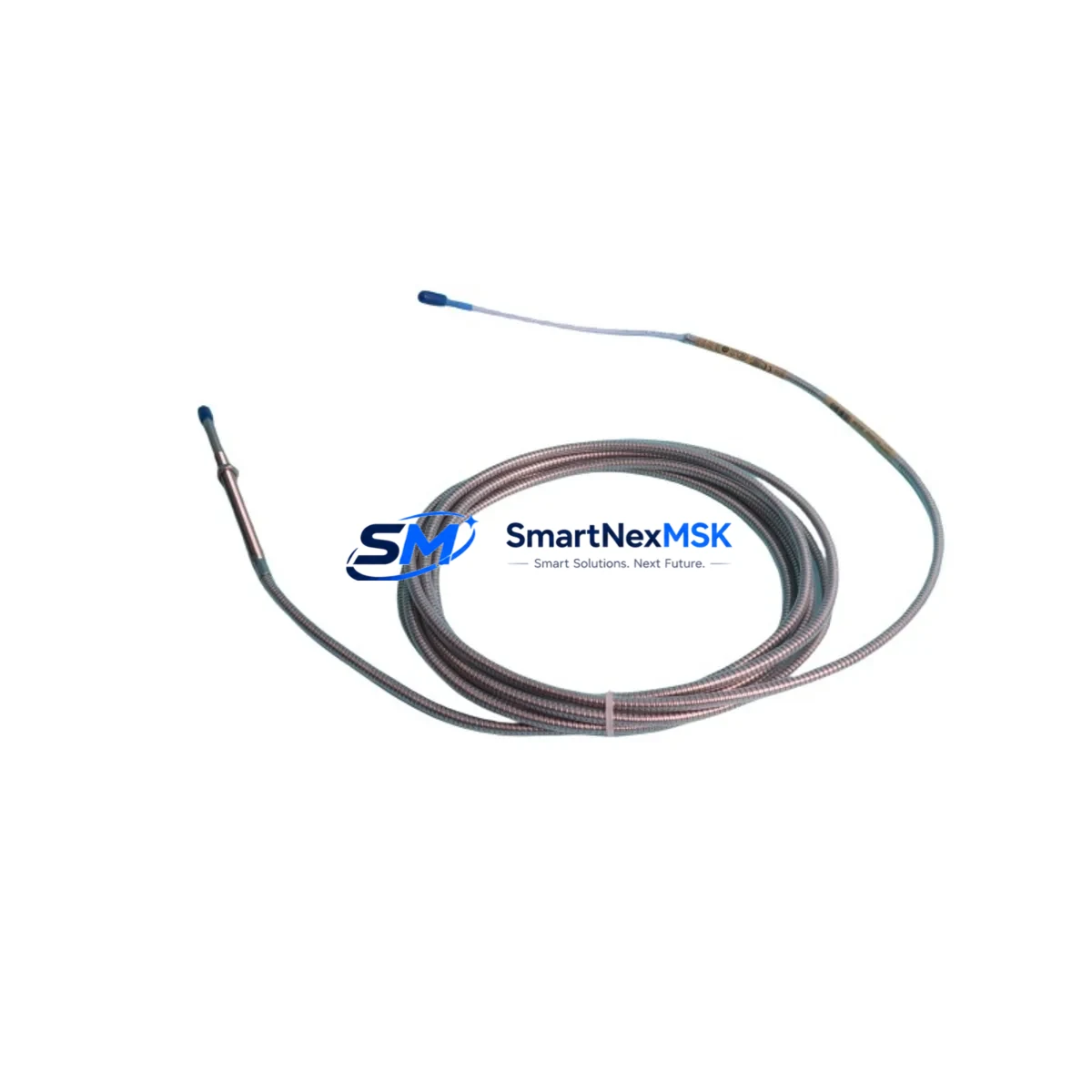
Bently Nevada 330104-00-05-50-02-05 Retrofit-Ready Proximity Transducer for 3300 XL Control Systems
The Bently Nevada 330104-00-05-50-02-05 is an 8mm proximity transducer designed for continuous shaft vibration and position monitoring within the 3300 XL Series machinery protection platform. As legacy installations age and OEM support windows close, this component has become a critical retrofit solution for plants seeking to extend the operational life of their existing 3300 XL monitoring infrastructure without committing to a full system overhaul. Whether you are replacing a failed sensor on a turbine train, upgrading a deteriorated cable assembly, or restoring a mothballed unit to service, the 330104-00-05-50-02-05 provides a direct, compatible replacement path that preserves your existing wiring topology, signal conditioning chain, and monitor configuration.
For maintenance and procurement engineers managing aging rotating machinery protection systems, sourcing a verified, tested replacement for this transducer is often the fastest route to restoring full protection coverage and returning equipment to safe operation. SMARTNEXMSK maintains ready stock of the 330104-00-05-50-02-05 with full pre-shipment electrical verification, ensuring that every unit dispatched meets the original Bently Nevada performance specification for gap voltage, sensitivity, and frequency response.
Upgrade Compatibility Table
| Parameter | Specification / Detail |
|---|---|
| SKU / Part Number | 330104-00-05-50-02-05 |
| Brand / Series | Bently Nevada / 3300 XL |
| Transducer Type | 8mm Eddy-Current Proximity Transducer |
| Nominal Gap Voltage | −10 VDC (at 1.0 mm nominal gap) |
| Sensitivity | 7.87 V/mm (200 mV/mil) |
| Cable Length | 5.0 m (integral armored cable) |
| Connector | Standard BNC / TNC compatible with 3300 XL extension cable |
| Compatible Monitors | 3300 XL 8mm Monitor, 3500/40M, 3500/42M, 3500/45, 3500/46M |
| Compatible Extension Cable | 330130 series (5 m, 9 m options) |
| Compatible Driver / Proximitor | 330180 Proximitor Sensor |
| Installation Interface | M10 × 1 threaded mount; locknut included |
| Target Material Compatibility | AISI 4140 steel (standard); verify for non-standard alloys |
| Operating Temperature | −35 °C to +120 °C |
| Retrofit Recommendation | Direct drop-in for 330104-00-05-50-02-05; verify gap setting post-installation |
| Commissioning Note | Re-zero gap voltage at monitor after replacement; check OK relay status |
| Warranty | 12 Months from shipment date |
| Origin | United States |
| Pre-Shipment Test | Electrical continuity, insulation resistance, gap voltage output verified |
Retrofit Planning for Existing Automation Systems
A successful retrofit of the 330104-00-05-50-02-05 in an operating plant requires more than simply swapping the transducer tip. Engineers should approach the replacement as a mini-system audit, verifying the integrity of every component in the measurement chain before returning the loop to service.
Begin with the 330130 series extension cable. Armored extension cables in long-running installations frequently suffer from jacket cracking, connector corrosion, or shield continuity loss — any of which will introduce noise or offset errors that mimic a failing transducer. If the extension cable has been in service for more than five years or has been routed through a high-vibration conduit, replace it concurrently with the transducer to avoid a repeat outage.
Next, inspect the 330180 Proximitor Sensor (driver). The Proximitor converts the transducer’s raw impedance signal into a calibrated DC voltage output. A degraded Proximitor will produce incorrect gap voltage readings even with a new transducer installed, leading to false OK/Not-OK relay states at the 3300 XL 8mm Monitor or downstream 3500/40M Proximitor I/O Module. Verify the Proximitor’s output voltage at the nominal gap before closing the cabinet.
At the monitor level, confirm that the 3500 Rack backplane connections are secure and that the monitor card is seated correctly. Loose backplane contacts in older 3500 racks are a common source of intermittent channel faults that are incorrectly attributed to the transducer. While the rack is open, inspect the 3500/20 Rack Interface Module for firmware currency and verify that the Modbus or Ethernet communication link to the plant DCS or historian is active.
For plants running a System 1 condition monitoring platform, confirm that the channel configuration database reflects the new transducer’s serial number and calibration constants. Failure to update the asset record can result in incorrect alarm setpoints being applied to the replacement unit. If the plant uses a 3500/92 Communication Gateway Module for Modbus TCP or PROFIBUS integration, verify that the gateway’s channel mapping is intact after any rack power cycle performed during the retrofit.
Where the retrofit is part of a broader control cabinet upgrade — for example, migrating from a standalone 3300 XL panel to a fully integrated 3500 rack — also review the 3500/15 Power Supply Module capacity. Adding transducer channels increases the aggregate current draw on the rack power bus; confirm that the existing power supply has sufficient headroom before energizing the upgraded configuration. A 3500/05 Rack Interface Module with updated firmware may also be required to support expanded channel counts in modernized rack configurations.
Finally, document the as-found and as-left gap voltage readings, OK relay status, and alarm setpoint verification results in the plant’s maintenance management system. This record supports future audits, insurance inspections, and API 670 compliance reviews.
Downtime Control During System Migration
Minimizing production downtime during a proximity transducer retrofit depends on preparation, parts availability, and a disciplined commissioning sequence. The following workflow is recommended for replacing the 330104-00-05-50-02-05 in a live rotating machinery protection system:
Pre-outage preparation: Confirm that the replacement transducer, extension cable, and any associated Proximitor have been received, inspected, and electrically verified before the maintenance window opens. Record the existing gap voltage, alarm setpoints, and OK relay configuration from the 3300 XL or 3500 monitor so that these values can be restored exactly after replacement. Download and archive the current System 1 asset configuration if applicable.
Isolation and removal: De-energize the monitor channel (not the full rack, if bypass is available) and apply the appropriate lock-out/tag-out procedure. Disconnect the extension cable at the Proximitor junction. Remove the transducer from the machine casing, noting the as-found gap measurement for comparison with the replacement unit’s installation target.
Installation and gap setting: Install the 330104-00-05-50-02-05 replacement, threading it to the correct depth to achieve the nominal −10 VDC gap voltage output. Use a calibrated DC voltmeter at the Proximitor output terminals to confirm the gap voltage before securing the locknut. Do not rely solely on the monitor’s front-panel display during initial gap setting, as display update rates may mask transient readings.
Commissioning and return to service: Re-energize the monitor channel and verify that the OK relay closes within the expected timeframe. Confirm that vibration and position readings are within normal baseline range for the machine at rest. Clear any latched alarms at the 3500 rack or DCS interface. Restore the System 1 asset record and verify that the historian is logging the channel correctly. Document all as-left readings before releasing the machine for restart.
By staging replacement parts in advance and following a structured commissioning sequence, most 330104-00-05-50-02-05 retrofits can be completed within a single planned maintenance shift, with no unplanned extension of the outage window.
Retrofit Support FAQ
Q1: Is the 330104-00-05-50-02-05 a direct replacement for all 3300 XL 8mm proximity transducer variants?
The 330104-00-05-50-02-05 is a specific configuration within the 3300 XL 8mm transducer family, defined by its cable length (5.0 m), connector type, and temperature rating. Before ordering, verify that the cable length and connector configuration match your installation. Alternative configurations within the 330104 family (e.g., different cable lengths or high-temperature ratings) are available — contact our technical team with your existing part number for confirmation.
Q2: How is the unit tested before shipment?
Every 330104-00-05-50-02-05 dispatched by SMARTNEXMSK undergoes pre-shipment electrical verification including continuity check, insulation resistance measurement, and gap voltage output test against a calibrated target. A test report is available upon request. Units are shipped in anti-static packaging with protective end caps on the transducer tip and connector.
Q3: What is covered under the 12-month warranty?
The 12-month warranty covers manufacturing defects, electrical performance deviations from the published Bently Nevada specification, and premature failure under normal operating conditions. It does not cover damage resulting from incorrect installation, gap setting errors, mechanical impact, or operation outside the rated temperature and environmental limits. Warranty claims are processed with return of the defective unit and a completed failure report.
Q4: Can you supply the 330104-00-05-50-02-05 for long-term maintenance contracts or blanket purchase orders?
Yes. SMARTNEXMSK supports long-term supply agreements for critical spare parts including the 330104-00-05-50-02-05. We can reserve allocated stock, provide scheduled delivery against a blanket order, and issue certificates of conformance for each shipment. Contact sales@smartnexmsk.com to discuss volume pricing and supply terms.
© 2026 SMARTNEXMSK. All rights reserved.
Original Source: https://smartnexmsk.com
Contact: sales@smartnexmsk.com | +86 18259474341


