Bently Nevada 330104-00-05-50-02-CN Maintenance-Ready Spare for 3300 XL Automation
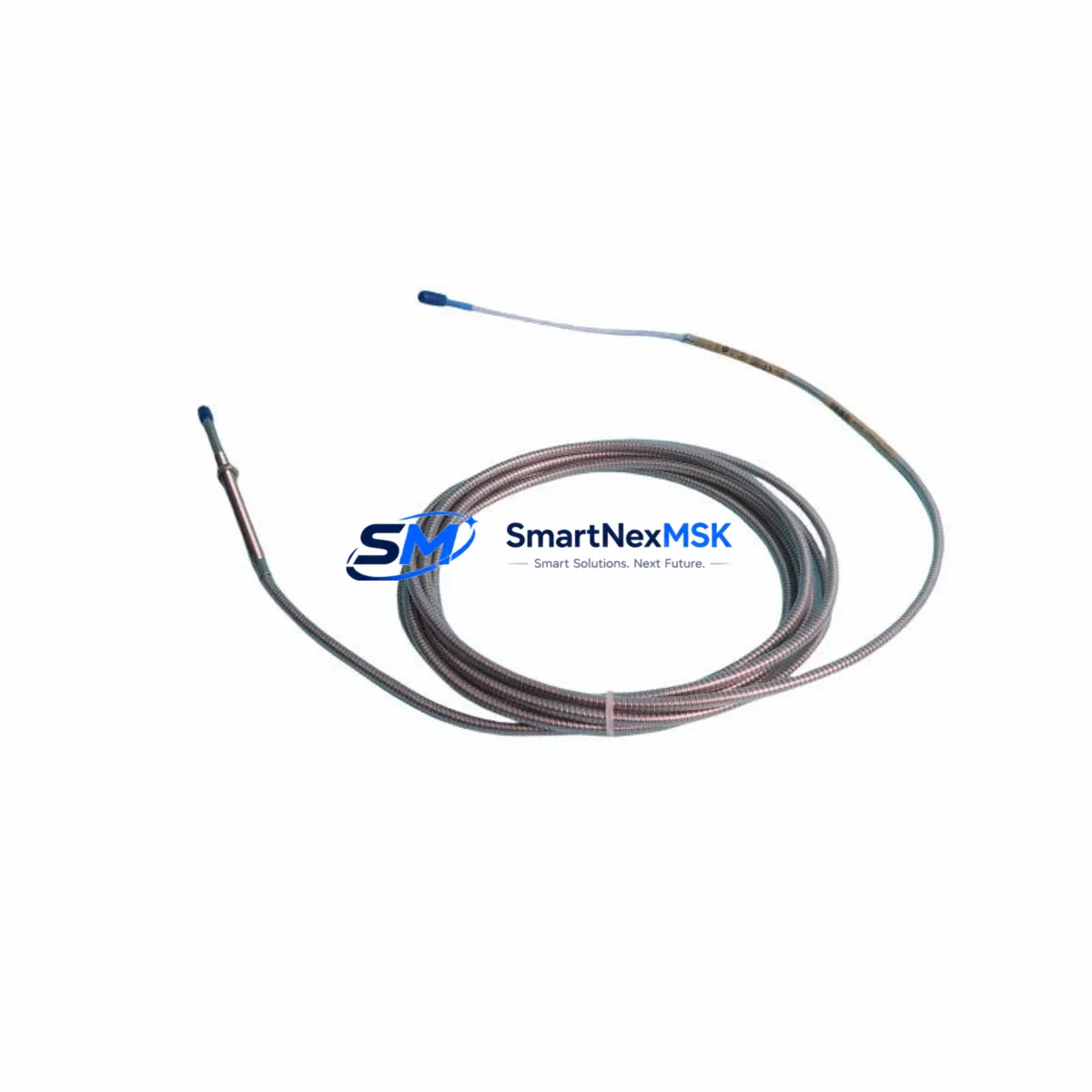
The Bently Nevada 330104-00-05-50-02-CN is an original 8mm proximity transducer engineered for the 3300 XL continuous vibration monitoring system. Designed for shaft radial vibration, axial position, and differential expansion measurement on rotating machinery, this transducer is a critical spare for any maintenance team responsible for turbines, compressors, pumps, and motors in continuous-process industries. When a proximity transducer fails or drifts out of calibration, the result is unplanned downtime, false trips, or — worse — undetected rotor damage. Stocking the 330104-00-05-50-02-CN as a ready-to-deploy spare is the single most effective step a maintenance engineer can take to protect machine availability and reduce mean time to repair (MTTR).
This unit ships fully tested against Bently Nevada factory specifications, including gap voltage linearity, sensitivity (200 mV/mil), and frequency response. Each unit is verified for compatibility with the 3300 XL proximitor/driver system before dispatch. A 12-month warranty covers all units against manufacturing defects, giving procurement engineers confidence in long-term supply continuity.
Spare Maintenance Table
| Parameter | Specification |
|---|---|
| Part Number | 330104-00-05-50-02-CN |
| Brand | Bently Nevada |
| Series | 3300 XL |
| Transducer Type | Eddy-Current Proximity Transducer, 8mm |
| Sensitivity | 200 mV/mil (7.87 V/mm) |
| Linear Range | 0 to 90 mil (0 to 2.29 mm) |
| Supply Voltage | -24 VDC (nominal) |
| Operating Temperature | -35°C to +121°C |
| Cable Length | 5m (standard) |
| Connector | 2-pin MIL-C-5015 style |
| Compatible System | Bently Nevada 3300 XL Proximitor/Driver |
| Application | Radial vibration, axial position, differential expansion |
| Target Material | Steel, stainless steel, iron-based alloys |
| Installation | Threaded body, locknut mounting, 8mm probe tip |
| Origin | USA (Original Bently Nevada) |
| Warranty | 12 Months |
| Condition | New, factory-tested |
Maintenance Planning for Continuous Operation
When a maintenance or reliability engineer schedules a planned outage or responds to a vibration alarm, replacing the 330104-00-05-50-02-CN transducer is rarely the only task on the checklist. A thorough inspection of the surrounding measurement loop is essential to prevent repeat failures and ensure the system returns to full accuracy after the repair.
Start with the 3300 XL Proximitor/Driver (such as the 330180-X1-05 or 330130-040-00-00 series): verify the driver output voltage and confirm the gap voltage at the installed probe tip is within the linear range (typically -10 VDC ±0.5 V at the nominal gap). A drifted or failed driver is a common root cause of apparent transducer faults. Next, inspect the extension cable — the 330130 series armored extension cables are the correct match for this transducer and must be checked for continuity, insulation resistance, and connector integrity, as cable damage from vibration or heat is a frequent failure mode in turbine bearing housings.
Check the 3300/16 or 3500/42 monitor card in the rack: confirm channel configuration, alert and danger setpoints, and that the OK relay output is functioning correctly. If the machine uses a 3500 Series rack, inspect the 3500/20 power supply module for output voltage stability — a marginal power supply can cause intermittent transducer faults that are misdiagnosed as probe failures. Review the 3500/22M transient data interface if the system logs startup transients, as corrupted configuration data can mask real vibration events.
For machines with thrust bearing monitoring, simultaneously inspect the 330104-00-05-50-02-CN paired axial transducer and its companion channel. Axial and radial channels are often wired through the same junction box — inspect terminal blocks, cable glands, and grounding connections at this point. Loose or corroded terminals in the junction box are a leading cause of noise and signal dropout in proximity measurement loops.
If the control system integrates vibration data into a DCS or safety PLC via 4–20 mA or relay outputs, verify the signal conditioning at the I/O module level. Confirm that the analog input card is reading within expected range and that no channel has been placed in bypass or override mode during the fault period. For systems using Modbus or FOUNDATION Fieldbus communication from the 3500 rack, check the communication module configuration and verify that the host system is receiving live data after the transducer replacement.
Finally, after reinstallation, perform a static gap check using a calibrated voltmeter before returning the machine to service. Document the as-found and as-left gap voltages in the maintenance record. This step is mandatory for any site that operates under ISO 13373 or API 670 vibration monitoring standards.
Site Replacement Workflow
Step 1 — Isolate and de-energize: Place the affected monitor channel in bypass at the 3500/3300 rack before removing the transducer. This prevents a false danger trip during the replacement procedure.
Step 2 — Record as-found condition: Note the gap voltage, vibration reading, and any active alarms. Photograph the probe tip and target surface for the maintenance record.
Step 3 — Remove the old transducer: Loosen the locknut and unthread the 330104-00-05-50-02-CN probe body. Inspect the target area on the shaft for scoring, runout, or contamination that may have contributed to the fault.
Step 4 — Install the replacement unit: Thread the new 330104-00-05-50-02-CN to the nominal gap (typically 50 mil / 1.27 mm for an 8mm probe on steel). Verify gap voltage with a calibrated voltmeter: target -10.0 VDC ±0.5 V. Tighten the locknut to the specified torque.
Step 5 — Reconnect and verify: Reconnect the extension cable and confirm continuity. Remove the channel bypass at the rack. Confirm the monitor displays a valid vibration reading and the OK LED is illuminated.
Step 6 — Return to service and document: Log the as-left gap voltage, confirm no active alarms, and update the CMMS with the replacement date, part number, and technician ID. Schedule the next inspection interval per the site’s predictive maintenance program.
Using an original Bently Nevada 330104-00-05-50-02-CN replacement — rather than an uncertified substitute — ensures the measurement loop maintains its API 670 compliance and that the system’s vibration trip setpoints remain valid without recalibration of the entire channel.
Spare Parts Support FAQ
Q1: Is the 330104-00-05-50-02-CN compatible with both 3300 XL and 3500 Series monitoring racks?
Yes. The 330104-00-05-50-02-CN is designed for the 3300 XL proximitor/driver system. It is also compatible with 3500 Series racks when used with the correct 3500/42 proximity monitor card and the matching 330130 series extension cable. Always verify the driver part number and cable length match the installed system configuration before ordering.
Q2: What is the recommended spare parts inventory strategy for this transducer?
For critical rotating machinery (turbines, compressors, large pumps), best practice is to stock a minimum of one spare 330104-00-05-50-02-CN per monitored machine, plus one spare extension cable and one spare proximitor/driver. For plants with multiple identical machines, a pooled inventory of 2–3 units per machine type is recommended to cover simultaneous failures during a major outage.
Q3: How is each unit tested before shipment?
Every 330104-00-05-50-02-CN unit is bench-tested for gap voltage linearity, sensitivity (200 mV/mil), and OK output function prior to dispatch. Test results are available upon request. Units are shipped in anti-static packaging with a calibration reference card.
Q4: What does the 12-month warranty cover?
The 12-month warranty covers manufacturing defects, sensitivity drift beyond factory tolerance, and connector or cable integrity failures under normal operating conditions. It does not cover damage from incorrect installation, mechanical impact, or operation outside the specified temperature and voltage range. Warranty claims are processed within 5 business days with advance replacement available for critical applications.
© 2026 SMARTNEXMSK. All rights reserved.
Original Source: https://smartnexmsk.com
Contact: sales@smartnexmsk.com | +86 18259474341


