Bently Nevada 330104-00-07-05-01-CN 3300 XL Retrofit-Ready Proximity Transducer: Compatible Modernization for Legacy Vibration Monitoring Systems
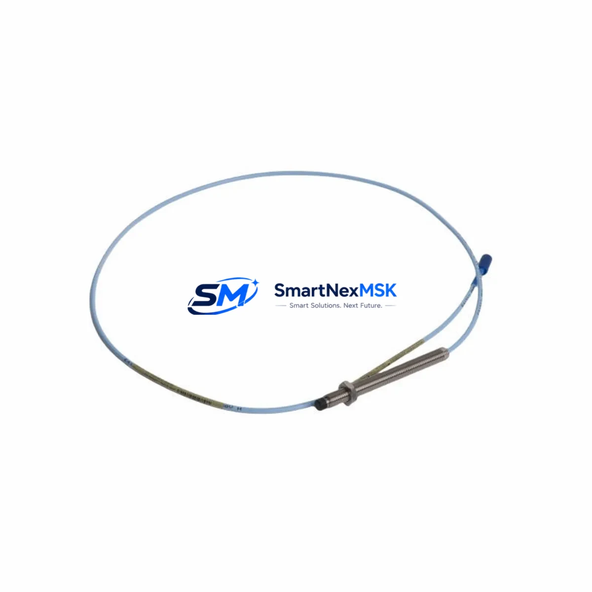
The Bently Nevada 330104-00-07-05-01-CN is a 3300 XL Series proximity transducer engineered for continuous shaft vibration and position monitoring in rotating machinery applications. As legacy 3300 Series installations reach end-of-life or face discontinued spare parts availability, this unit serves as a verified retrofit-ready replacement that preserves existing wiring infrastructure, signal conditioning compatibility, and rack-mount architecture — minimizing engineering rework and unplanned downtime during system modernization.
This transducer operates on the standard Bently Nevada eddy-current sensing principle, delivering a linear output voltage proportional to the gap between the probe tip and the observed conductive target surface. The -CN suffix designates a connector-terminated cable assembly, compatible with the standard 3300 XL extension cable and driver/proximitor configurations used across the 3300 XL platform. Engineers replacing failed or obsolete units from earlier 3300 Series generations will find this model maintains backward signal compatibility with the 3300/16 Monitor, 3300/25 Monitor, and 3300/55 Monitor rack cards, provided the proximitor output range and gap voltage are re-verified during commissioning.
When planning a retrofit around the 330104-00-07-05-01-CN, the first step is confirming the existing extension cable length and part number — typically a 330130-Series or 330140-Series cable — to ensure the total system length (probe + extension) matches the proximitor calibration range. The proximitor itself, such as the 330180-X1-05 or 330190-Series driver, must be verified for compatibility with the new probe’s sensitivity factor (typically 7.87 V/mm or 200 mV/mil). Mismatched sensitivity factors between probe and proximitor are a leading cause of calibration drift after replacement.
For installations integrated into a System 1 condition monitoring platform or a 3500 Series rack, the signal output from this transducer feeds directly into the 3500/42M Proximitor/Seismic Monitor or 3500/40M Proximitor Monitor cards. Engineers should verify the OK relay logic, gap voltage setpoints, and alert/danger thresholds stored in the rack configuration before hot-swapping the transducer. Where the existing rack uses a 3300/20 Keyphasor Module for phase reference, the replacement transducer installation should not disturb the Keyphasor probe gap, as this affects all phase-referenced measurements across the rack.
In control cabinet environments where the 330104-00-07-05-01-CN is mounted alongside power supply modules such as the 3300/05 Power Supply or 3500/15 Power Supply, technicians should confirm that the cabinet’s DC bus voltage remains within the proximitor’s supply specification (typically -24 VDC ±10%) under full rack load. Voltage sag during peak demand can cause false OK dropouts and nuisance trips during commissioning.
For plants migrating from older 7200 Series or 3000 Series Bently Nevada hardware to the 3300 XL platform, the 330104-00-07-05-01-CN is a key component in the migration bill of materials. The migration typically also involves replacing the 7200/14-01-01-00 proximity probe, 7200/60-01-00 extension cable, and 7200/04-01-00 proximitor with their 3300 XL equivalents, and updating the System 1 database node configuration to reflect the new transducer sensitivity and gap range. HMI screens built on GE iFIX, Wonderware InTouch, or Emerson DeltaV that display vibration trend data should be reviewed to confirm engineering unit scaling remains correct after the transducer swap.
All units supplied by SMARTNEXMSK are sourced from verified industrial supply channels, individually inspected for connector integrity and cable jacket condition, and shipped with a 12-month warranty covering manufacturing defects and signal output conformance. Pre-shipment functional testing includes gap voltage linearity verification across the rated sensing range.
Upgrade Compatibility Table
| Parameter | Detail |
|---|---|
| Part Number | 330104-00-07-05-01-CN |
| Series | Bently Nevada 3300 XL |
| Sensing Technology | Eddy-Current Proximity (Non-contact) |
| Output Sensitivity | 7.87 V/mm (200 mV/mil) nominal |
| Cable Termination | -CN Connector (standard 3300 XL) |
| Compatible Extension Cables | 330130-Series, 330140-Series |
| Compatible Proximitors/Drivers | 330180-X1-05, 330190-Series |
| Compatible Monitor Cards | 3500/42M, 3500/40M, 3300/16, 3300/25, 3300/55 |
| Supply Voltage | -24 VDC ±10% (via proximitor) |
| Installation Type | Rack-mount / Field-mount (existing bracket reuse) |
| Retrofit Compatibility | Drop-in for 3300 XL; migration path from 7200 Series / 3000 Series |
| Commissioning Requirement | Gap voltage re-verification, OK relay setpoint confirmation |
| Warranty | 12 Months — Manufacturing Defects & Signal Output Conformance |
Retrofit Planning for Existing Automation Systems
A successful retrofit centered on the 330104-00-07-05-01-CN requires a structured bill of materials review before any field work begins. In a typical 3300 XL rack installation, the transducer works in concert with the 330130-080-00-CN extension cable, the 330180-X1-05 proximitor, and the 3500/42M monitor card housed in a 3500/05 Rack Interface Module chassis. Each of these components has defined interface specifications that must be cross-checked against the replacement transducer’s sensitivity and cable length to ensure the overall system gain remains within calibrated limits.
Where the existing installation uses a 3300/20 Keyphasor Module for phase-referenced vibration analysis, the Keyphasor probe gap must be independently verified and must not be disturbed during the transducer replacement. Similarly, if the rack includes a 3500/22M Transient Data Interface for startup/shutdown data capture, the new transducer’s signal should be validated against the stored baseline waveforms in System 1 before returning the machine to service.
For plants running Emerson DeltaV or Honeywell Experion PKS as the primary DCS, the vibration monitor rack typically communicates via Modbus RTU or OPC-DA to the DCS historian. After transducer replacement, the communication link should be verified by confirming live vibration values appear correctly in the DCS faceplate and that no stale or frozen values are present in the historian. If the plant uses a 3500/92 Communication Gateway, the gateway configuration file should be reviewed to confirm the channel mapping for the replaced transducer channel remains correct.
In control cabinet environments, the 3300/05 Power Supply or 3500/15 Power Supply rail voltage should be load-tested after the new transducer is connected to confirm no voltage droop occurs under full rack load. Technicians should also inspect the terminal block wiring — typically Phoenix Contact or Weidmüller DIN-rail terminal strips — for corrosion or loose ferrules before reconnecting the transducer cable, as poor terminal contact is a common source of intermittent OK relay faults in legacy installations.
Downtime Control During System Migration
Minimizing production downtime during a 330104-00-07-05-01-CN replacement requires pre-staging all replacement components and completing as much bench verification as possible before the maintenance window opens. The replacement transducer, extension cable, and proximitor should be bench-tested as a matched set using a calibration target to confirm gap voltage linearity before the unit is taken to the field. This eliminates the most common cause of extended commissioning time — discovering a sensitivity mismatch only after the machine is shut down.
During the maintenance window, the existing transducer should be removed without disturbing the mounting bracket or conduit entry, as reusing the original bracket eliminates the need for re-drilling or re-tapping the machine casing. The replacement probe should be installed to the same gap distance as the original (typically 1.0–1.5 mm for a 5 mm probe), verified with a digital gap meter before the extension cable is reconnected. The proximitor OK LED should illuminate within seconds of power restoration if the gap and cable length are within specification.
Before returning the machine to service, the monitor card’s alert and danger setpoints should be confirmed against the plant’s vibration acceptance criteria, and a short coast-down or bump test should be performed to verify that the vibration trend displayed in System 1 or the DCS historian matches expected baseline behavior. Documenting the as-left gap voltage and OK status in the plant’s maintenance management system (CMMS) creates a reference baseline for future predictive maintenance intervals, reducing the risk of unplanned trips caused by probe wear or gap drift over time.
Retrofit Support FAQ
Q: Is the 330104-00-07-05-01-CN a direct drop-in replacement for earlier 3300 Series proximity probes?
A: For most 3300 XL rack installations, yes — provided the extension cable length and proximitor model are compatible with the 3300 XL sensitivity specification. For installations migrating from the older 7200 Series or 3000 Series, the proximitor and extension cable must also be replaced to match the 3300 XL system gain. SMARTNEXMSK can advise on the complete replacement bill of materials based on your existing part numbers.
Q: What wiring changes are required when replacing the transducer?
A: The -CN connector termination is designed for tool-free mating with the standard 3300 XL extension cable connector. No field wiring modification is required at the transducer-to-extension cable interface. At the proximitor end, the existing terminal block wiring (typically a 3-wire shielded connection: +, -, and shield/drain) should be inspected for ferrule condition and re-torqued to the terminal manufacturer’s specification before reconnection.
Q: How is commissioning verified after installation?
A: Commissioning verification involves three steps: (1) confirming the gap voltage at the proximitor output falls within the linear range for the installed gap distance, (2) confirming the monitor card’s OK relay is energized and no fault codes are present in the 3500 rack display or System 1 software, and (3) performing a functional vibration check (bump test or coast-down) to confirm the vibration signal responds correctly to shaft movement. All units supplied by SMARTNEXMSK are pre-tested for gap voltage linearity before shipment.
Q: What does the 12-month warranty cover?
A: The 12-month warranty covers manufacturing defects in materials and workmanship, including connector integrity, cable jacket condition, and signal output conformance to the 3300 XL sensitivity specification. Warranty claims are supported by SMARTNEXMSK’s technical team, with replacement units dispatched within 3 business days of a confirmed warranty fault. The warranty period begins from the date of shipment.
© 2026 SMARTNEXMSK. All rights reserved.
Original Source: https://smartnexmsk.com
Contact: sales@smartnexmsk.com | +86 18259474341


