Bently Nevada 330104-00-09-90-02-00 Retrofit-Ready Proximity Probe for 3300 XL Control Systems
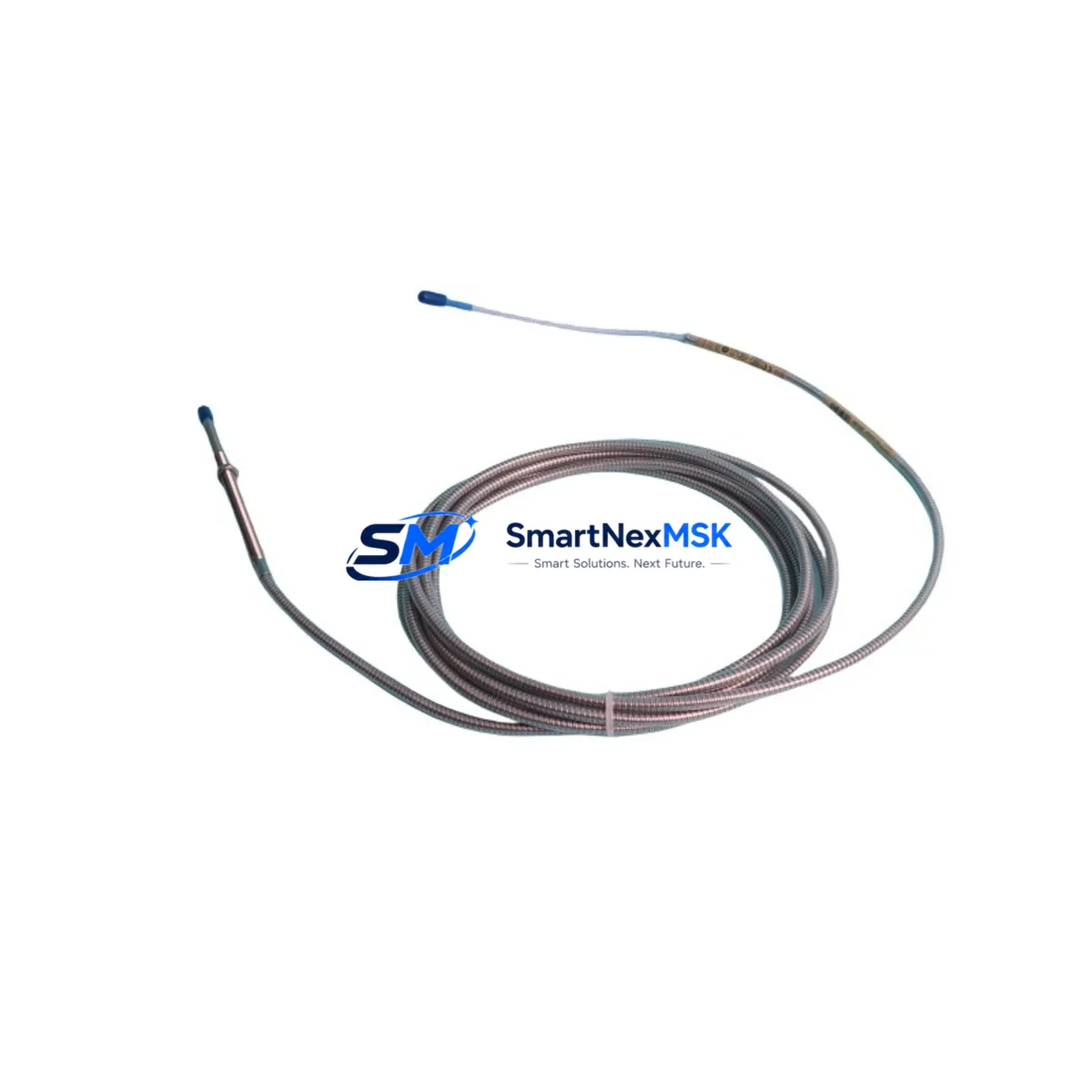
The Bently Nevada 330104-00-09-90-02-00 is an 8mm eddy-current proximity probe engineered for the 3300 XL Series vibration monitoring platform. As legacy machinery protection systems reach end-of-service milestones, this probe serves as a verified drop-in replacement for discontinued or worn-out field sensors — enabling smooth retrofits without requiring full system overhauls or PLC reprogramming. Whether you are upgrading an aging turbine protection rack, restoring a compressor monitoring loop, or migrating from an older 3300 Series installation to the 3300 XL architecture, this probe delivers the dimensional accuracy, sensitivity, and signal integrity required for continuous, uninterrupted plant operation.
Each unit ships pre-tested and calibrated to Bently Nevada factory specifications. The 330104-00-09-90-02-00 features a 9mm cable length configuration with standard 90-degree connector orientation, making it directly interchangeable with original-fit installations in most turbine, compressor, pump, and gearbox monitoring enclosures. The probe integrates seamlessly with the 3300 XL proximitor/seismic module, including the 3300/16 and 3300/20 series signal conditioning cards, without requiring gap voltage recalibration in most standard installations.
Upgrade Compatibility Table
| Parameter | Details |
|---|---|
| SKU / Part Number | 330104-00-09-90-02-00 |
| Compatible Platform | Bently Nevada 3300 XL Series |
| Probe Diameter | 8mm |
| Cable Length | 9m (standard) |
| Connector Orientation | 90-degree |
| Signal Conditioning | Compatible with 3300/16, 3300/20 proximitor modules |
| Installation Type | Direct replacement, no bracket modification required |
| Communication / Output | Analog voltage output (–24 VDC bias) |
| Retrofit Recommendation | Verified drop-in for 330104 series probes |
| Commissioning Note | Verify gap voltage (–10 VDC ±0.5 V) after installation |
| Warranty | 12 Months |
Retrofit Planning for Existing Automation Systems
Successful retrofit of the 330104-00-09-90-02-00 into an operating plant requires careful pre-installation planning across several interdependent system layers. Before removing the legacy probe, engineers should document the existing gap voltage reading at the proximitor output terminal — typically measured at the 3300/16 proximitor/seismic module’s BNC or terminal block output — and record the baseline vibration amplitude and DC gap values from the System 1 condition monitoring software or equivalent historian.
The probe mounts into the existing transducer bracket without modification in most standard installations. However, if the original probe was from an earlier 330100 or 330103 series, verify that the extension cable — commonly the 330130-080-00-00 or 330130-045-00-00 armored extension — is compatible with the 330104 driver circuit. The proximitor module, such as the 3300/16-02-01-01-00-00 or 3300/20 series, must be confirmed operational before probe swap to isolate the fault source accurately.
For installations where the 3300 XL rack also houses a 3500/42M proximitor monitor card, note that the probe signal is routed through the I/O module backplane. Confirm that the rack’s 3500/05 power supply module is delivering stable –24 VDC to the probe circuit before commissioning the replacement. In multi-channel racks, adjacent channels monitoring axial position via 330980-50-05 thrust probes or radial vibration via paired 330104 probes should remain energized during the swap to maintain continuous protection on the remaining measurement points.
Where the control system integrates with a DCS — such as a Honeywell Experion PKS, Emerson DeltaV, or ABB 800xA — the 4–20 mA or hardwired relay outputs from the 3500 rack to the DCS I/O marshalling cabinet should be verified for continuity before and after probe replacement. If the plant uses a Modbus RTU or FOUNDATION Fieldbus communication link between the 3500 rack and the DCS, confirm that the communication module — typically the 3500/92 communication gateway — remains online throughout the swap to avoid nuisance alarms or spurious trips at the DCS level.
For facilities running legacy HMI screens built on Wonderware InTouch or GE iFIX, the vibration trend tags associated with the replaced probe channel should be monitored in real time during commissioning to confirm that the new probe’s gap voltage and sensitivity factor match the historian’s expected engineering unit range. If the HMI displays a raw millivolt value rather than a converted engineering unit, recalibrate the scaling block in the DCS or PLC tag database to reflect the new probe’s actual sensitivity (typically 7.87 V/mm for standard 8mm probes).
Downtime Control During System Migration
Minimizing unplanned downtime during a proximity probe replacement requires a structured hot-swap or controlled-outage procedure. Where plant safety systems permit, the 330104-00-09-90-02-00 can be replaced during a brief controlled outage window — typically 30 to 90 minutes — without requiring a full machinery train shutdown if the protection relay logic allows channel bypass during maintenance mode.
Before initiating the swap, place the affected channel in bypass mode at the 3500/42M monitor or equivalent voting logic module to prevent a spurious trip during probe removal. Document the original probe’s gap voltage, sensitivity, and OK status LED state. After installing the replacement 330104-00-09-90-02-00, restore the gap to the manufacturer-specified –10 VDC (±0.5 V) using a non-ferrous adjustment tool at the probe tip, then confirm the OK relay output is energized before removing the channel bypass.
All replacement units supplied by SMARTNEXMSK are bench-tested prior to shipment, including gap voltage linearity verification and OK circuit continuity checks, reducing the risk of commissioning failures in the field. This pre-shipment testing protocol, combined with the 12-month warranty coverage, ensures that replacement inventory can be staged in the maintenance storeroom with confidence for rapid deployment during the next planned or unplanned outage window.
Retrofit Support FAQ
Q1: Is the 330104-00-09-90-02-00 a direct replacement for the 330104-00-09-10-02-00?
A: The primary difference between the -90- and -10- connector orientation variants is the cable exit angle (90-degree vs. straight). In most installations, the -90- variant is interchangeable if the cable routing and bracket geometry allow. Confirm connector clearance before ordering.
Q2: Do I need to recalibrate the proximitor after replacing the probe?
A: In most cases, no full recalibration is required if the replacement probe is the same SKU and the extension cable is unchanged. However, always verify the gap voltage at the proximitor output terminal after installation and adjust the probe tip gap if the reading deviates more than ±0.5 V from the –10 VDC nominal.
Q3: What is included in the 12-month warranty?
A: The 12-month warranty covers manufacturing defects, OK circuit failure, and sensitivity deviation beyond ±5% of the rated 7.87 V/mm specification under normal operating conditions. It does not cover damage resulting from incorrect installation gap, reverse polarity wiring, or mechanical impact.
Q4: Can SMARTNEXMSK supply the matching extension cable and proximitor module?
A: Yes. We maintain stock of compatible 330130 series extension cables and 3300/16 and 3300/20 proximitor modules. Contact our sales team with your full rack configuration for a matched replacement kit quotation.
© 2026 SMARTNEXMSK. All rights reserved.
Original Source: https://smartnexmsk.com
Contact: sales@smartnexmsk.com | +86 18259474341


