Bently Nevada 330104-00-11-05-01-CN Spare 3300 XL Automation
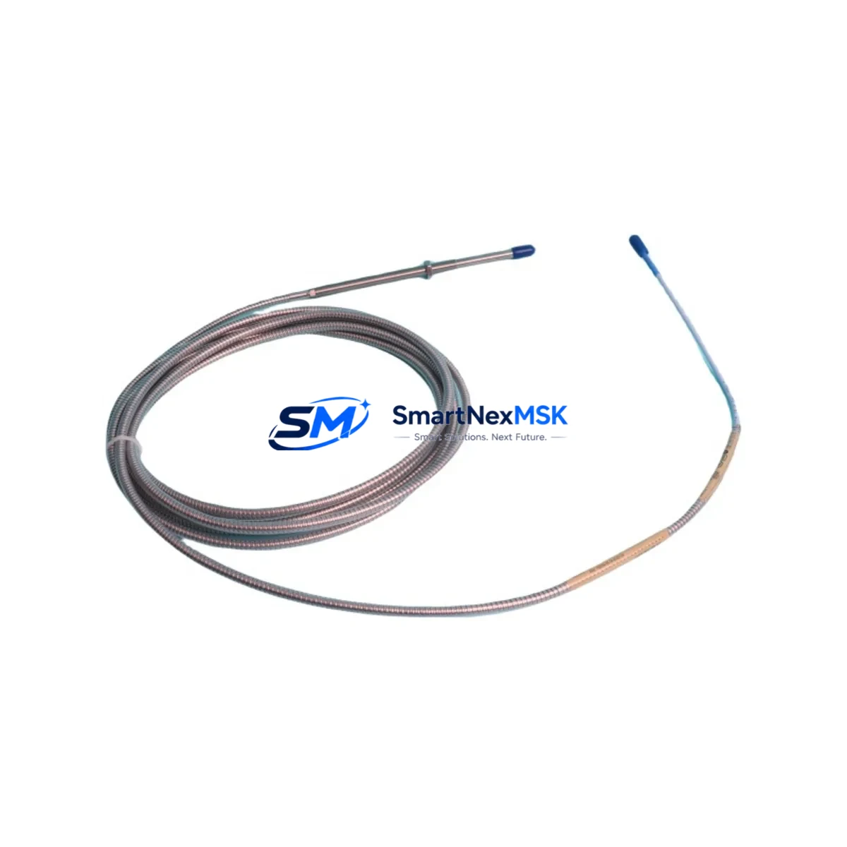
The Bently Nevada 330104-00-11-05-01-CN is an original eddy-current proximity transducer engineered for the 3300 XL continuous vibration monitoring system. Designed for shaft displacement and radial vibration measurement on rotating machinery — including steam turbines, gas compressors, centrifugal pumps, and large induction motors — this transducer is a critical spare for any maintenance team operating Bently Nevada-based condition monitoring infrastructure.
When a proximity transducer fails or drifts out of calibration, the entire vibration channel goes blind. Undetected shaft displacement can escalate into bearing failure, seal damage, or catastrophic rotor contact within hours. Holding a verified replacement of the 330104-00-11-05-01-CN in your spare parts cabinet is the single most effective way to restore full monitoring coverage and resume safe operation without waiting on lead times.
This unit ships tested, with original factory specifications confirmed. Each unit carries a 12-month warranty covering manufacturing defects and functional performance. Worldwide logistics support is available for urgent shutdown recovery scenarios.
Spare Maintenance Table
| Parameter | Specification |
|---|---|
| SKU / Part Number | 330104-00-11-05-01-CN |
| Brand | Bently Nevada |
| Series | 3300 XL |
| Product Type | Eddy-Current Proximity Transducer |
| Measurement Target | Shaft radial displacement, axial position |
| Sensitivity | 200 mV/mil (7.87 V/mm) nominal |
| Operating Gap Range | 0 – 90 mil (0 – 2.29 mm) |
| Linear Range | 10 – 90 mil (0.25 – 2.29 mm) |
| Supply Voltage | −24 VDC (via 3300 XL driver/monitor) |
| Cable Length | 5 m (standard; extension cable compatible) |
| Connector Type | Coaxial, 3-pin MIL-spec |
| Target Material Compatibility | AISI 4140 steel (standard); other alloys require calibration |
| Temperature Range | −35 °C to +177 °C (probe tip) |
| IP Rating | IP67 (probe body) |
| Mounting Thread | 3/8–24 UNF |
| Compatible Monitor | 3300 XL 8mm Proximity Transducer System |
| Origin | USA |
| Warranty | 12 Months |
| Condition | Original Spare — Tested Before Shipment |
Maintenance Planning for Continuous Operation
Replacing the 330104-00-11-05-01-CN transducer in the field is rarely an isolated task. A disciplined maintenance engineer will treat the transducer swap as an opportunity to audit the entire vibration channel and adjacent control cabinet components. Begin by inspecting the 3300 XL extension cable (typically 330130-series) for jacket cracking, connector corrosion, or impedance drift — a degraded cable is the most common cause of false gap readings after a transducer replacement.
Next, verify the 3300 XL proximitor/driver module (such as the 330180 or 330185 series) output voltage at the OK relay terminal. A proximitor that is marginal will pass bench tests but fail under thermal load during normal operation. If the machine has been running with a suspected transducer fault for more than a few weeks, the proximitor should be treated as a co-suspect and a spare held on-site.
For installations where the 3300 XL monitor feeds a 3500 Series rack — including the 3500/42M Proximitor Monitor or 3500/22M Transient Data Interface — confirm that the channel configuration in the rack software still matches the replacement transducer’s sensitivity and gap range. A mismatch here will produce incorrect engineering-unit readings even with a perfectly functional new transducer.
During the same cabinet inspection, check the 24 VDC power supply module feeding the proximitor rail. Voltage sag below −22 VDC or ripple above 100 mV peak-to-peak will degrade transducer linearity and trigger nuisance OK-relay trips. Spare power supply cards for the 3500 rack (3500/15 Power Supply) should be part of any critical-machine spare parts kit.
If the machine is also equipped with a 3300 XL velocity transducer or a 330500-series accelerometer on the same bearing housing, inspect those sensors simultaneously — thermal cycling and vibration fatigue affect all sensors on a bearing cap equally. Replacing one sensor while leaving aged neighbors in place is a common cause of repeat callouts within the same maintenance window.
For plants running a System 1 Evolution or System 1 Optimizer condition monitoring platform, confirm that the new transducer’s channel is re-zeroed and the baseline waveform is re-captured after installation. Failure to update the baseline will mask early-warning trend deviations for weeks after the repair.
Finally, review the terminal strip and field wiring inside the junction box at the machine skid. Corroded terminals, loose ferrules, or undersized shielded cable are frequent contributors to high-frequency noise on the proximity signal. A signal isolator or conditioner may be warranted if the cable run exceeds 30 m or passes through a high-EMI environment near VFDs or large contactors.
Site Replacement Workflow
Step 1 — Isolation and lockout: Coordinate with operations to place the machine in a safe state. For online-replaceable channels (where the monitor supports hot-swap), confirm the bypass procedure with the control room before disconnecting the transducer.
Step 2 — Gap measurement before removal: Record the installed gap voltage from the proximitor output (typically −10 to −18 VDC for a healthy gap). This baseline confirms whether the old transducer was actually faulty or whether the fault lies upstream in the cable or proximitor.
Step 3 — Mechanical installation: Thread the 330104-00-11-05-01-CN into the bracket using the 3/8–24 UNF thread. Set the initial gap to the midpoint of the linear range (approximately 50 mil / 1.27 mm) using a non-ferrous feeler gauge or a calibrated gap-setting tool. Torque the locknut to the manufacturer’s specification — typically 20–25 in-lb — to prevent gap drift under vibration.
Step 4 — Electrical reconnection and verification: Reconnect the extension cable and confirm the proximitor output voltage falls within the expected gap range. Use a calibrated digital multimeter; do not rely solely on the monitor’s front-panel display for initial verification.
Step 5 — System re-commissioning: Clear any latched alarms in the 3500 rack or DCS, re-enable the channel, and confirm that the OK relay energizes. Monitor the first 30 minutes of operation for any trend anomalies before returning the machine to full load.
This workflow minimizes total downtime to under two hours for a prepared maintenance team with the correct spare on hand — compared to days or weeks waiting for an emergency procurement.
Spare Parts Support FAQ
Q1: Is the 330104-00-11-05-01-CN a direct drop-in replacement for older 330104-series transducers?
Yes. The 330104-00-11-05-01-CN is backward-compatible with all 3300 XL 8mm proximity transducer installations. The -CN suffix denotes the connector variant; confirm your existing extension cable connector type before ordering to ensure a tool-free field connection.
Q2: What does the 12-month warranty cover?
The warranty covers manufacturing defects, functional performance deviations from published specifications, and OK-relay failures under normal operating conditions. It does not cover physical damage from improper installation, over-torquing, or exposure to fluids outside the rated IP67 envelope. Each unit is tested before shipment and ships with a test record on request.
Q3: How should I manage inventory levels for this transducer?
For critical rotating machinery (turbines, compressors, large pumps), industry best practice is to hold a minimum of one spare per monitored machine, with a site-level buffer of two to three units for plants with five or more monitored assets. Given typical lead times for OEM procurement, a local spare eliminates the risk of extended unmonitored operation during a shutdown.
Q4: Can this transducer be used with non-Bently Nevada monitors or DCS systems?
The 330104-00-11-05-01-CN outputs a standard eddy-current signal compatible with any monitor that accepts a −24 VDC-powered, 200 mV/mil proximity transducer input. Compatibility with third-party monitors (Emerson, Metso, Honeywell, ABB) should be verified against the monitor’s input specification sheet. Contact our technical team for application-specific compatibility confirmation before ordering.
© 2026 SMARTNEXMSK. All rights reserved.
Original Source: https://smartnexmsk.com
Contact: sales@smartnexmsk.com | +86 18259474341


