Bently Nevada 330104-00-13-05-01-CN 3300 XL Maintenance-Ready Spare for 3300 XL Automation
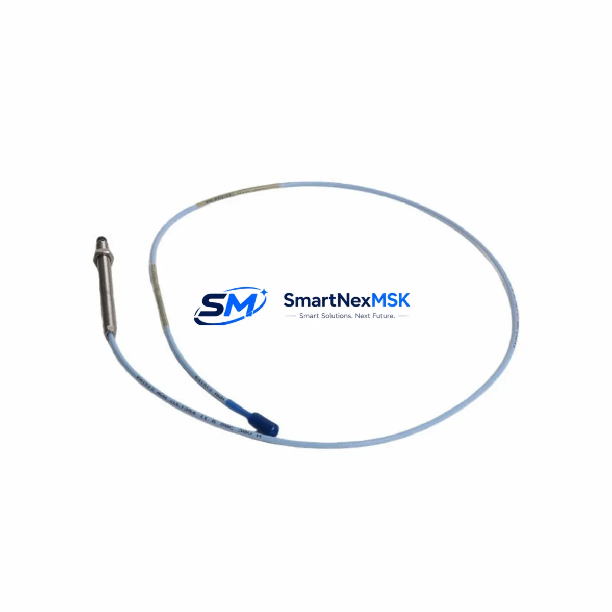
The Bently Nevada 330104-00-13-05-01-CN is an original 8mm eddy current proximity transducer engineered for the 3300 XL Series continuous machinery protection system. Designed to deliver precise non-contact vibration and position measurement on rotating equipment — including turbines, compressors, pumps, and motors — this transducer is a critical spare for any facility operating Bently Nevada-based condition monitoring infrastructure. When a transducer fails or drifts out of calibration, the result is not just a measurement gap: it is an unplanned shutdown, a missed alarm threshold, and a potential safety event. Holding a verified, tested replacement in your spare parts inventory is the single most effective way to compress mean time to repair (MTTR) and restore continuous operation.
The 330104-00-13-05-01-CN is compatible with the Bently Nevada 3300 XL 8mm Proximity Transducer System, which includes the extension cable (330130 series) and the proximitor sensor (330180 series). The complete measurement chain — transducer, extension cable, and proximitor — must be treated as a matched system. When replacing this transducer on-site, maintenance engineers should verify that the paired extension cable and proximitor are within specification and have not accumulated excessive hours or thermal stress. Replacing only the transducer while leaving a degraded extension cable or a drifting proximitor in circuit will not restore system accuracy and may introduce new fault conditions.
This unit ships pre-tested against Bently Nevada factory electrical specifications, with a 12-month warranty covering manufacturing defects and electrical performance. Each unit is individually inspected prior to dispatch to ensure gap voltage, sensitivity, and linearity are within the published 3300 XL system tolerances. Fast dispatch is available for urgent maintenance requirements.
Spare Maintenance Table
| Parameter | Specification |
|---|---|
| Part Number / SKU | 330104-00-13-05-01-CN |
| Brand | Bently Nevada |
| Series | 3300 XL 8mm Proximity Transducer System |
| Transducer Type | Eddy Current (Non-Contact) |
| Probe Diameter | 8mm |
| Nominal Sensitivity | 7.87 V/mm (200 mV/mil) |
| Linear Range | 0.25 mm – 2.25 mm (10 – 90 mil) |
| Supply Voltage | -24 VDC (via Proximitor) |
| Output Signal | DC voltage proportional to gap distance |
| Temperature Range | -35°C to +177°C (probe tip) |
| API Standard | API 670 (Machinery Protection Systems) |
| Compatibility | 3300 XL Proximitor 330180 series; Extension Cable 330130 series |
| Installation | Threaded probe body, locknut mounting, radial or axial orientation |
| Application | Turbines, compressors, pumps, motors, gearboxes — radial vibration & axial position |
| Origin | CN |
| Warranty | 12 Months — covers electrical performance and manufacturing defects |
| Pre-Shipment Test | Yes — gap voltage, sensitivity, and linearity verified |
Maintenance Planning for Continuous Operation
Effective maintenance planning for a 3300 XL-based protection system requires treating the proximity transducer not as an isolated component but as part of an integrated measurement chain. When scheduling a planned outage or responding to a transducer alarm, maintenance engineers should simultaneously inspect and — where hours or condition warrant — replace the following associated components:
The 330130 Series Extension Cable connects the probe to the proximitor and is subject to mechanical fatigue, connector corrosion, and insulation degradation in high-temperature or high-vibration environments. A transducer replacement that leaves a compromised extension cable in service will produce erratic gap voltage readings. Similarly, the 330180 Series Proximitor Sensor should be bench-tested for output linearity and noise floor before being returned to service after any transducer swap.
At the control cabinet level, the 3500/42M Proximitor/Seismic Monitor or equivalent 3500 series rack module processes the transducer signal and generates alarm and trip outputs. Inspect the monitor card for firmware currency, channel configuration, and relay output integrity. The 3500/20 Rack Interface Module (RIM) and 3500/22M Transient Data Interface should be checked for communication health and event log integrity during the same maintenance window.
Power supply integrity is equally critical. The 3500/15 Power Supply Module feeding the rack should be verified for output voltage stability and ripple, as power supply degradation is a common root cause of false transducer alarms. Where redundant power supplies are installed, both units should be load-tested. Terminal blocks and field wiring within the junction box — including shielding continuity and grounding — should be inspected for corrosion, loose terminations, and moisture ingress.
For facilities running legacy Bently Nevada 3300 Series (non-XL) systems alongside newer 3300 XL infrastructure, maintaining a cross-compatible spare inventory that includes both 330100 Series (standard 3300) and 330104 Series (3300 XL) transducers reduces the risk of a stockout during an emergency. Signal isolators and barriers in the field wiring circuit should also be included in the periodic inspection checklist, particularly in hazardous area installations where intrinsic safety barriers govern the permissible energy in the transducer loop.
Site Replacement Workflow
Step 1 — Isolation and Permit: Obtain a valid work permit and isolate the measurement channel at the 3500 rack monitor. Place the channel in bypass mode to prevent a spurious trip during transducer removal. Document the current gap voltage and alarm setpoints before disconnecting.
Step 2 — Transducer Removal: Loosen the locknut and carefully unthread the 330104-00-13-05-01-CN probe from the mounting bracket. Inspect the probe tip for physical damage, target surface condition, and any signs of rubbing contact. Record the installed gap (typically 1.0–1.5 mm for radial vibration applications) for reference during reinstallation.
Step 3 — Extension Cable Inspection: Disconnect the extension cable at both the probe connector and the proximitor input. Inspect the cable jacket, connectors, and shield termination. Measure cable resistance and insulation resistance. Replace the 330130 series extension cable if any anomaly is found — do not reuse a suspect cable with a new transducer.
Step 4 — New Transducer Installation: Thread the replacement 330104-00-13-05-01-CN into the mounting bracket. Set the gap to the documented or design value using a feeler gauge or gap voltage measurement at the proximitor output. Tighten the locknut to the specified torque. Reconnect the extension cable.
Step 5 — System Verification: With the channel still in bypass, power the proximitor and verify gap voltage is within the linear range (typically -10 VDC ± 1 VDC at nominal gap for a -24 VDC supply). Confirm sensitivity by manually varying the gap and observing the output. Remove bypass, restore alarm setpoints, and confirm the channel is active and healthy in the 3500 rack display.
Step 6 — Documentation: Record the replacement in the equipment maintenance log, including the new transducer serial number, installed gap voltage, date, and technician. Update the spare parts inventory to trigger reorder of the consumed unit.
Spare Parts Support FAQ
Q1: Is the 330104-00-13-05-01-CN a direct drop-in replacement for the standard 330104-00-13-05-01?
The -CN suffix designates the country-of-origin variant for customs and export documentation purposes. The electrical specifications, mechanical dimensions, and system compatibility are identical to the standard 330104-00-13-05-01. It is a direct functional replacement within the 3300 XL 8mm Proximity Transducer System.
Q2: What is the recommended spare parts holding strategy for 3300 XL transducers?
For critical rotating equipment (turbines, compressors), industry best practice is to hold a minimum of one spare transducer per monitored shaft, plus one spare extension cable and one spare proximitor per rack. For facilities with 10 or more monitored machines, a pooled spare strategy with a minimum of 3–5 units of the 330104 series is recommended to cover simultaneous failures during a major outage event.
Q3: How is each unit tested before shipment?
Every 330104-00-13-05-01-CN unit is bench-tested prior to dispatch using a calibrated target and a reference proximitor. Gap voltage, output sensitivity (V/mm), and linearity across the full measurement range are verified against Bently Nevada published specifications. A test report is available upon request. Units that do not meet specification are quarantined and not shipped.
Q4: What does the 12-month warranty cover?
The 12-month warranty covers electrical performance failures and manufacturing defects under normal operating conditions. It does not cover damage resulting from physical impact, incorrect installation gap, operation outside the specified temperature range, or use with incompatible extension cables or proximitors. Warranty claims are processed with return of the defective unit and provision of the original purchase documentation.
© 2026 SMARTNEXMSK. All rights reserved.
Original Source: https://smartnexmsk.com
Contact: sales@smartnexmsk.com | +86 18259474341


