Bently Nevada 330104-00-14-05-01-00 Retrofit-Ready Proximity Transducer for 3300 XL Control Systems
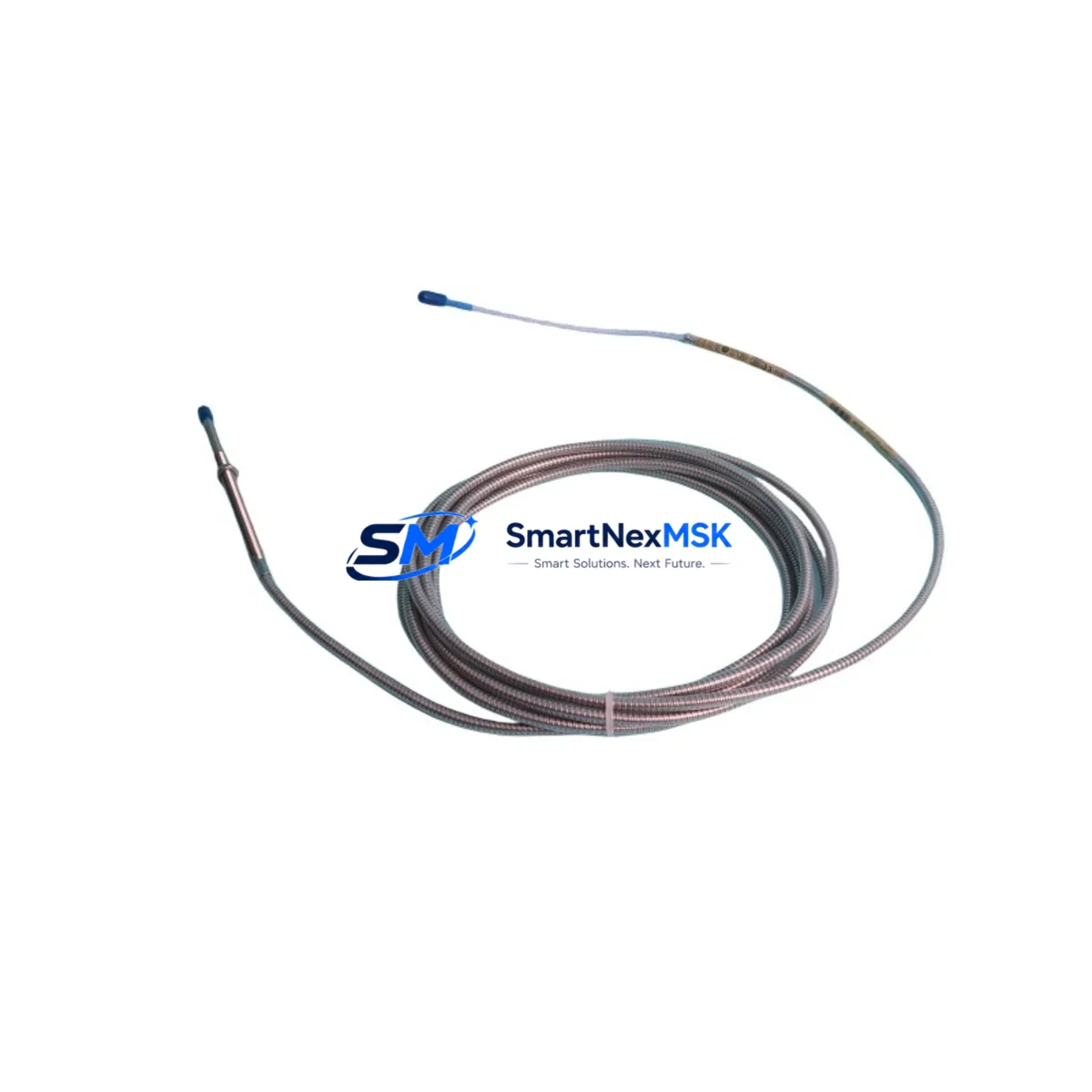
The Bently Nevada 330104-00-14-05-01-00 is an 8mm eddy-current proximity transducer engineered for the 3300 XL Series vibration monitoring platform. As legacy machinery protection systems approach end-of-service life, this transducer serves as a direct, wiring-compatible replacement for discontinued 3300 Series predecessors, enabling plant engineers to modernize rotating equipment monitoring without redesigning the entire control cabinet or rewriting existing System 1 software configurations.
Designed for continuous shaft displacement and radial vibration measurement on turbines, compressors, pumps, and gearboxes, the 330104-00-14-05-01-00 operates within the standard Bently Nevada signal chain: transducer → extension cable (330130 series) → Proximitor® sensor (330180 or 330185 series). This three-component architecture is preserved across the retrofit, meaning existing cable runs and junction box terminations typically remain unchanged. Engineers replacing a failed or obsolete 3300 Series transducer can reuse the existing 330130-080-00-00 extension cable and the 3300 XL Proximitor® already mounted in the rack, dramatically reducing installation time and minimizing exposure to unplanned downtime.
Before committing to a swap, retrofit planners should verify four critical parameters: (1) the gap voltage setpoint stored in the 3500/40M or 3500/42M monitor module, which must align with the new transducer’s sensitivity curve (typically −7.87 V/mm); (2) the terminal block wiring at the field junction box, confirming shield continuity and correct polarity on the coaxial connector; (3) the Proximitor® power supply rail—usually −24 VDC supplied by the 3500 rack’s internal power module (3500/15 or 3500/05)—to ensure adequate current headroom when multiple channels are active; and (4) the OK relay setpoint in the monitor, which governs the not-OK voltage threshold and must be recalibrated if the replacement transducer exhibits a slightly different static gap characteristic.
Upgrade Compatibility Table
| Parameter | 330104-00-14-05-01-00 (This Unit) | Notes / Retrofit Guidance |
|---|---|---|
| Transducer Diameter | 8 mm | Matches standard 3300 XL probe bore; no re-machining required |
| Sensitivity | 7.87 V/mm (200 mV/mil) | Recalibrate gap voltage in monitor after installation |
| Operating Range | 0.25 – 2.54 mm (10 – 100 mil) | Verify existing gap setting falls within this window |
| Compatible Extension Cable | 330130 Series (specify length) | Reuse existing cable if undamaged; inspect connector pins |
| Compatible Proximitor® | 330180 / 330185 Series | No firmware update required for standard 3300 XL racks |
| Monitor Compatibility | 3500/40M, 3500/42M, 3300 XL | Confirm OK relay threshold after replacement |
| Power Supply Requirement | −24 VDC (via rack) | Supplied by 3500/15 or 3500/05 power module |
| Communication Protocol | Analog (−24 VDC / 4–20 mA via monitor) | No protocol migration needed; monitor handles signal conversion |
| Installation Type | Threaded probe, armored cable | Torque to manufacturer spec; do not over-tighten |
| Warranty | 12 Months | Covers manufacturing defects; includes pre-shipment functional test |
Retrofit Planning for Existing Automation Systems
A successful retrofit of the 330104-00-14-05-01-00 into an aging machinery protection system requires a structured approach that accounts for every component in the signal path. Begin at the 3500 rack: confirm the 3500/05 or 3500/15 power module is supplying stable −24 VDC to the transducer channel. A degraded power module is a common root cause of false not-OK alarms that are misdiagnosed as transducer failure. If the rack also houses a 3500/20 or 3500/22 communication gateway module, verify that the Modbus or OPC-DA link to the plant DCS remains active throughout the swap—most 3500 racks support hot-swap of individual monitor cards without dropping the communication bus.
At the field junction box, inspect the 330130 extension cable for jacket abrasion, moisture ingress at the Belden-style coaxial connector, and continuity of the drain wire. A compromised extension cable will introduce noise into the gap voltage signal and cause erratic vibration readings even with a brand-new transducer. If the cable is suspect, replace it with a matched-length 330130-080-00-00 or 330130-050-00-00 unit before installing the new probe.
For plants running System 1 Evolution software, the transducer replacement does not require a database configuration change provided the channel sensitivity and range remain identical. However, if the site is migrating from an older System 1 v5.x installation to System 1 Evolution, this retrofit window is an ideal time to update the point configuration, verify the historian tag mapping, and confirm that the HMI trend displays on the operator workstation reflect the correct engineering units. Coordinate with the control room operator to suppress the affected channel alarm in the DCS—typically a Honeywell Experion PKS or Emerson DeltaV node—before pulling the probe to avoid nuisance trips on the safety instrumented system.
I/O expansion considerations arise when the retrofit is part of a broader platform upgrade. If the site is consolidating multiple legacy 3300 Series racks into a single 3500 rack, the 3500/40M monitor module supports up to two transducer channels per card, and the 3500/42M supports four. Plan the channel assignment carefully to balance the rack’s internal bus load. The 3500 rack’s backplane can accommodate up to 16 monitor modules, and adding a 3500/32 relay output module allows the upgraded system to drive existing hardwired shutdown logic without rewiring the motor control center.
Commissioning after installation follows a standard Bently Nevada gap-setting procedure: power the Proximitor®, measure the DC gap voltage with a calibrated multimeter at the monitor’s BNC test point, and adjust the probe axial position until the gap voltage reads within the specified window (typically −10.0 V ± 0.5 V for a 1.0 mm gap). Record the as-found and as-left gap voltages in the maintenance management system. Perform a static calibration check using a certified gap simulator before returning the machine to service.
Downtime Control During System Migration
Minimizing production loss during a transducer replacement on a critical rotating machine requires pre-staging all replacement components—the 330104-00-14-05-01-00 transducer, the matched extension cable, and any required probe holder or adaptor sleeve—before the maintenance window opens. A typical hot-standby strategy involves pre-wiring the new transducer to a spare channel on the 3500/40M monitor, verifying the gap voltage offline, and then executing a rapid channel switchover rather than a physical probe swap under time pressure.
Where process conditions permit a brief coastdown, the preferred sequence is: (1) notify the DCS operator to place the affected vibration channel in bypass mode; (2) isolate the Proximitor® power at the rack terminal block rather than de-energizing the entire 3500 rack, preserving all other monitoring channels; (3) swap the transducer and extension cable; (4) restore power and verify gap voltage; (5) release the channel from bypass and confirm alarm setpoints are active before restarting the machine. This sequence typically takes 20–40 minutes for an experienced technician and avoids the multi-hour outage associated with a full rack power cycle.
For plants with redundant machinery trains, coordinate the replacement to occur while the standby train is carrying full load. Document the as-found condition of the failed transducer—including the gap voltage at failure, any physical damage to the probe tip, and the extension cable connector condition—to support root-cause analysis and future spare parts planning. Maintaining a minimum of two 330104-00-14-05-01-00 units in the site warehouse, alongside matched 330130 extension cables and a spare 330180 Proximitor®, is recommended for critical service applications.
Retrofit Support FAQ
Q1: Is the 330104-00-14-05-01-00 a direct drop-in replacement for the older 330104-00-14-05-00-00?
A: Yes. The -01-00 revision maintains the same 8mm probe diameter, 200 mV/mil sensitivity, and threaded mounting dimensions as the earlier revision. The extension cable connector and Proximitor® interface are unchanged. A gap voltage verification and OK relay check are still recommended after any transducer replacement.
Q2: Do I need to reconfigure the 3500/40M monitor after replacing the transducer?
A: In most cases, no. If the replacement transducer has the same sensitivity and the gap is set to the same nominal value, the existing monitor configuration remains valid. However, if the as-left gap voltage differs from the as-found value by more than ±0.5 V, recalibrate the OK threshold in the monitor configuration software to prevent nuisance not-OK alarms.
Q3: What pre-shipment testing is performed on this unit?
A: Each 330104-00-14-05-01-00 unit undergoes a functional output test verifying DC sensitivity, frequency response, and connector integrity before shipment. A test certificate is available upon request. The unit is covered by a 12-month warranty against manufacturing defects from the date of shipment.
Q4: Can this transducer be used with a non-Bently Nevada Proximitor® or third-party monitor?
A: The 330104-00-14-05-01-00 is optimized for use with Bently Nevada 330180 and 330185 Proximitor® sensors and the 3500 Series monitor platform. Use with third-party drivers is possible if the driver supplies −24 VDC and is calibrated for 200 mV/mil sensitivity, but compatibility must be verified by the end user. SMARTNEXMSK recommends using matched Bently Nevada components for critical machinery protection applications.
© 2026 SMARTNEXMSK. All rights reserved.
Original Source: https://smartnexmsk.com
Contact: sales@smartnexmsk.com | +86 18259474341


