Bently Nevada 330104-00-14-50-02-00 Maintenance-Ready Spare for 3300 XL Automation
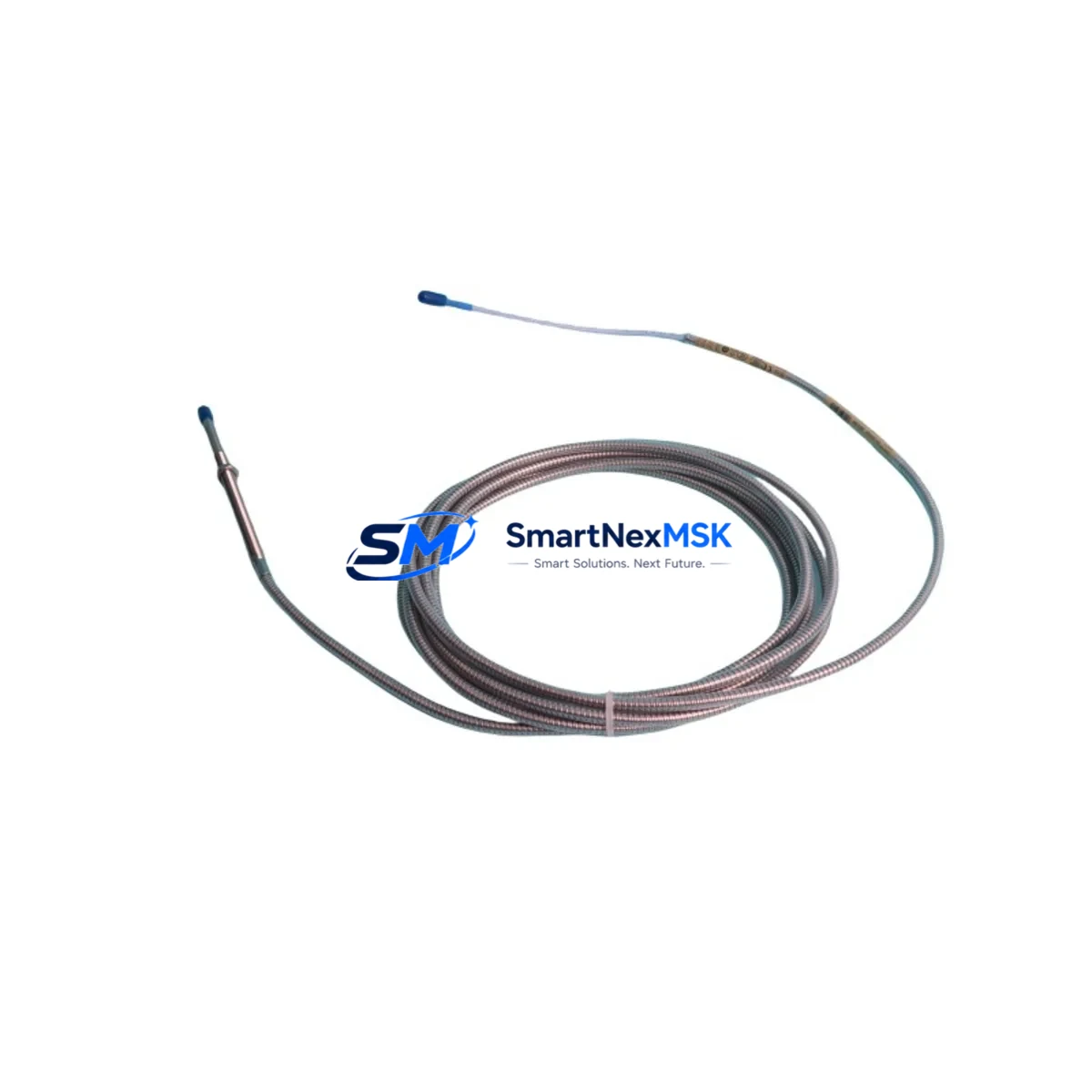
The Bently Nevada 330104-00-14-50-02-00 is an 8mm proximity transducer engineered for the 3300 XL Series continuous vibration monitoring system. In rotating machinery protection environments — turbines, compressors, pumps, and gearboxes — this transducer is a front-line component in shaft vibration and position measurement. When it fails or degrades, the entire monitoring loop is compromised, triggering unplanned shutdowns and exposing critical assets to damage. Stocking a verified original spare is the most effective strategy to minimize mean time to repair (MTTR) and maintain system integrity.
This unit ships fully tested, with a 12-month warranty from SMARTNEXMSK, and is sourced to meet OEM specifications for the 3300 XL platform. Whether you are executing a planned turnaround, responding to a trip event, or building a preventive maintenance spare kit, this transducer is ready for immediate deployment.
Spare Maintenance Table
| Parameter | Specification |
|---|---|
| Part Number | 330104-00-14-50-02-00 |
| Brand | Bently Nevada |
| Series | 3300 XL |
| Type | 8mm Proximity Transducer |
| Measurement | Shaft Radial Vibration & Position |
| Output Signal | -18 VDC nominal (eddy-current) |
| Cable Length | 5.0 m (standard) |
| Connector | 3-pin MIL-C-5015 compatible |
| Operating Temperature | -35°C to +121°C |
| Compatibility | 3300 XL Monitor, 3500/42 Proximitor, 3300/16 Monitor |
| Installation | Threaded mount, 8mm tip, standard gap 1.0–2.5 mm |
| Application | Turbines, Compressors, Pumps, Gearboxes |
| Origin | USA |
| Warranty | 12 Months (SMARTNEXMSK) |
| Pre-shipment Test | Yes — functional and output verified |
Maintenance Planning for Continuous Operation
Replacing the 330104-00-14-50-02-00 in the field is rarely an isolated task. Maintenance engineers and reliability teams should treat this transducer replacement as an opportunity to inspect the entire vibration monitoring loop and adjacent control infrastructure. A thorough site inspection during the same maintenance window reduces the risk of repeat trips and extends the operational life of the monitoring system.
Begin by inspecting the 330130-00-00-05-02-00 extension cable that connects the transducer to the Proximitor. Cable insulation degradation, connector corrosion, or mechanical damage at conduit entry points are common failure contributors that are often overlooked when only the transducer is replaced. Verify continuity and insulation resistance before reinstalling.
The 330180-X1-05 Proximitor sensor (or equivalent 3300 XL Proximitor) should be checked for output voltage stability and gap calibration. A worn or drifting Proximitor can cause false readings even with a new transducer installed. If the Proximitor has been in service for more than five years in a high-temperature environment, consider scheduling a replacement during the same outage.
At the monitor rack level, inspect the 3300/16 or 3500/42 monitor card for alarm setpoint integrity, relay output function, and communication status. Confirm that the OK relay and danger relay are operating correctly. If the system uses a 3500/20 rack power supply, verify output voltage under load — power supply degradation is a silent contributor to erratic vibration readings.
For plants running integrated DCS or safety systems, check the 4–20 mA output signal from the monitor to the DCS input card. Signal drift or ground loops at the signal isolator or barrier module can corrupt vibration data at the control room level without triggering a local alarm. A Zener barrier or galvanic isolator in the signal path should be tested for proper isolation resistance.
Terminal blocks and field wiring within the junction box or marshalling cabinet should be inspected for loose connections, oxidation, and correct labeling. In high-vibration environments, terminal screws can loosen over time, causing intermittent signal loss that is difficult to diagnose remotely. Torque-check all terminals in the vibration monitoring loop during this maintenance window.
If the machine is part of an API 670-compliant protection system, confirm that the overall system — including the 3500 rack keyphasor module and any thrust position transducers on the same shaft — is within calibration. A single out-of-calibration channel can mask real machinery faults or generate nuisance trips.
Finally, update the maintenance log with the new transducer serial number, installation date, gap measurement, and Proximitor output voltage. This data is essential for trending and for validating warranty coverage under the 12-month SMARTNEXMSK guarantee.
Site Replacement Workflow
Step 1 — Pre-replacement verification: Confirm the replacement part number matches the installed transducer. The 330104-00-14-50-02-00 is specific to the 8mm probe body with a 5.0 m cable. Do not substitute with a 5mm or 11mm variant without recalibrating the Proximitor gap voltage.
Step 2 — Safe isolation: Follow site LOTO (Lockout/Tagout) procedures. Isolate the monitor channel before disconnecting the transducer. Confirm the machine is at rest or that the monitoring system is in bypass mode to prevent false trip signals during removal.
Step 3 — Physical removal and inspection: Remove the transducer from the bearing housing. Inspect the probe tip for wear, pitting, or contamination. Inspect the threaded bore in the housing for damage. Clean the bore and apply anti-seize compound before installing the new transducer.
Step 4 — Installation and gap setting: Thread the new 330104-00-14-50-02-00 into the housing. Set the gap to the OEM-specified value (typically 1.0–2.5 mm, confirmed by Proximitor output voltage of -10.0 VDC ±0.5 VDC at nominal gap). Lock the transducer in position with the locknut.
Step 5 — System verification: Reconnect the extension cable and Proximitor. Power up the monitor channel and verify OK status. Confirm vibration reading is within baseline range before returning the machine to service. Document all measurements in the site CMMS.
This workflow is compatible with legacy 3300 Series installations and current 3500 Series racks, making the 330104-00-14-50-02-00 a reliable cross-generation spare for plants managing mixed-vintage Bently Nevada infrastructure.
Spare Parts Support FAQ
Q1: Is the 330104-00-14-50-02-00 compatible with both 3300 and 3500 Series monitors?
Yes. The 8mm proximity transducer is mechanically and electrically compatible with 3300 XL monitors and 3500/42 Proximitor-based systems. Always verify the Proximitor model and gap calibration range before installation to ensure signal accuracy.
Q2: What is the warranty coverage and how is it validated?
SMARTNEXMSK provides a 12-month warranty from the date of shipment. Each unit undergoes functional output testing before dispatch. Warranty claims require the original invoice and a description of the failure mode. Contact sales@smartnexmsk.com for RMA initiation.
Q3: How should this transducer be stored as a long-term spare?
Store in the original packaging in a dry, temperature-controlled environment (10°C–35°C), away from strong magnetic fields and mechanical shock. Inspect the probe tip and connector annually. Shelf life under proper storage conditions is typically 5+ years without performance degradation.
Q4: Can SMARTNEXMSK supply multiple units for a planned turnaround or spare kit?
Yes. Bulk orders and turnaround kits are supported. Contact sales@smartnexmsk.com or call +86 18259474341 to discuss quantity pricing, lead times, and consolidated shipment options for multi-unit spare packages.
© 2026 SMARTNEXMSK. All rights reserved.
Original Source: https://smartnexmsk.com
Contact: sales@smartnexmsk.com | +86 18259474341


