Bently Nevada 330104-00-15-05-01-CN 3300 XL Spare: Precision Spare Parts for Industrial Downtime Control
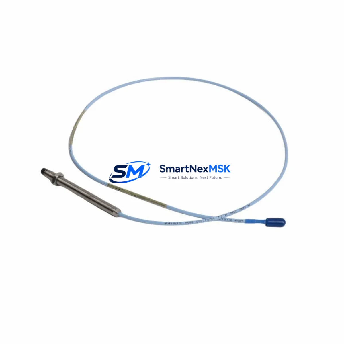
The Bently Nevada 330104-00-15-05-01-CN is an original eddy-current proximity probe engineered for the 3300 XL Series continuous machinery monitoring system. Designed for high-reliability vibration and position measurement in rotating machinery, this probe is a critical component in turbine protection panels, compressor monitoring racks, and pump condition monitoring loops across oil & gas, power generation, and petrochemical industries. When this probe fails or degrades, the entire vibration channel goes offline — exposing rotating assets to undetected fault conditions and potential catastrophic failure. Maintaining a verified spare on the shelf is not optional; it is a fundamental element of any serious predictive maintenance strategy.
SMARTNEXMSK supplies the 330104-00-15-05-01-CN as a tested, original spare with full traceability. Each unit undergoes pre-shipment electrical verification covering gap voltage output, sensitivity linearity, and cable continuity before dispatch. Our 12-month warranty covers manufacturing defects and performance deviation from published specifications, giving maintenance and procurement engineers confidence in every order.
Spare Maintenance Table
| Parameter | Specification |
|---|---|
| Part Number | 330104-00-15-05-01-CN |
| Brand | Bently Nevada |
| Series | 3300 XL |
| Type | Eddy-Current Proximity Probe |
| Probe Length | 15 cm (5.9 in) |
| Cable Length | 5 m (standard) |
| Tip Diameter | 8 mm |
| Sensitivity | 7.87 V/mm (200 mV/mil) |
| Linear Range | 0.25 – 2.25 mm (10 – 90 mil) |
| Supply Voltage | -24 VDC (nominal) |
| Output Voltage Range | -2 VDC to -18 VDC |
| Operating Temperature | -35°C to +177°C (probe tip) |
| Target Material Compatibility | Steel, Inconel, 4140 alloy steel |
| Connector Type | CN (Coaxial, standard Bently Nevada) |
| Ingress Protection | IP67 (probe body) |
| Mounting Thread | M10 × 1.0 |
| Application | Radial vibration, axial position, differential expansion |
| Compatible Monitor | 3300/16, 3300/20, 3300/25, 3500/40M, 3500/42M |
| Origin | USA |
| Warranty | 12 Months |
| Condition | Original, New / Tested Surplus |
Maintenance Planning for Continuous Operation
When a 330104-00-15-05-01-CN proximity probe is flagged during routine inspection or fails in service, the replacement event should trigger a broader review of the entire vibration monitoring channel. Maintenance engineers should not limit the scope to the probe alone. The 3300 XL system architecture means that probe performance is directly dependent on the condition of the extension cable — typically a 330130-series interconnect cable — and the Proximitor sensor, most commonly the 330180 or 330190 series. A degraded Proximitor will produce erroneous gap voltage even with a new probe installed, leading to false diagnostics and wasted downtime.
Beyond the probe-cable-Proximitor chain, the monitoring rack itself warrants inspection. The 3300/16 or 3300/20 monitor cards that receive the probe signal should be checked for input channel integrity, relay output status, and alarm setpoint configuration. If the plant runs a 3500 Series rack alongside legacy 3300 XL hardware, verify that the 3500/40M or 3500/42M monitor cards are correctly configured for the probe sensitivity constant (200 mV/mil) to avoid calibration mismatch after replacement.
Power supply integrity is equally critical. The -24 VDC supply rail feeding the Proximitor must be within tolerance; a sagging rail will shift the probe’s operating point and compress the linear measurement range. Inspect the rack power supply module — such as the 3500/15 or equivalent — and confirm output voltage under load. Fuse continuity on the supply rail should be verified before energizing a new probe assembly.
For plants operating in high-vibration or high-temperature environments, the probe mounting hardware — including the lock nut, jam nut, and armored conduit fittings — should be inspected for corrosion or mechanical damage during every probe replacement. The probe tip gap should be reset to the manufacturer-recommended nominal gap (typically 1.0–1.5 mm) using a calibrated gap-setting tool, and the gap voltage confirmed at the Proximitor output before the channel is returned to service.
Procurement engineers building a spare parts inventory for a 3300 XL or 3500 Series monitoring system should consider stocking the 330104-00-15-05-01-CN alongside complementary components: the 330130-series extension cable, 330180 Proximitor sensor, 3300/16 monitor card, 3500/15 power supply module, and a set of 3300 XL terminal board connectors. For plants with HMI integration, ensuring a spare 3500/92 communication gateway or equivalent Modbus/OPC interface card is available will prevent extended downtime if the data acquisition layer is also affected during a fault event.
Site Replacement Workflow
Step 1 — Isolation and Lockout: Follow site LOTO procedures. Isolate the -24 VDC supply to the affected Proximitor. Do not remove the probe under live power; the coaxial connector is not rated for hot-swap.
Step 2 — Channel Documentation: Record the existing gap voltage reading from the monitor display or DCS historian before disconnection. This baseline confirms the probe was within range and helps distinguish a probe fault from a target surface issue.
Step 3 — Probe Removal: Unscrew the probe from the mounting bracket using the correct spanner. Inspect the probe tip for impact damage, corrosion, or contamination. Inspect the target surface for scoring or runout anomalies that may have caused the probe failure.
Step 4 — Extension Cable Inspection: Disconnect the 330130-series extension cable at both ends. Check the coaxial connector pins for corrosion and the cable jacket for abrasion or crush damage. Replace the cable if any defect is found — a marginal cable will degrade the new probe’s performance.
Step 5 — New Probe Installation: Install the 330104-00-15-05-01-CN replacement. Set the probe tip gap to the nominal value specified in the machinery train data sheet (typically 1.0–1.5 mm). Torque the lock nut to specification.
Step 6 — Gap Voltage Verification: Restore -24 VDC supply. Measure the Proximitor output voltage with a calibrated DMM. Confirm the reading falls within the linear range (-10 VDC ± 1 VDC at nominal gap is typical). Compare against the pre-removal baseline.
Step 7 — Monitor Alarm Reset and Channel Return: Reset any latched alarms on the 3300 or 3500 monitor card. Confirm the channel is reading correctly on the DCS or plant historian. Return the machinery train to service only after the vibration channel has been verified stable for a minimum observation period per site procedures.
This workflow is compatible with legacy 3300 XL installations and current 3500 Series racks, ensuring system continuity without requiring firmware changes or reconfiguration when replacing like-for-like with the 330104-00-15-05-01-CN.
Spare Parts Support FAQ
Q1: Is the 330104-00-15-05-01-CN a direct drop-in replacement for older 330104-series probes?
Yes. The 330104-00-15-05-01-CN is dimensionally and electrically compatible with earlier 330104-series variants sharing the same probe length (15 cm), cable length (5 m), and CN connector type. Always confirm the sensitivity constant (200 mV/mil) matches the monitor card configuration before returning the channel to service. If the existing monitor is configured for a different sensitivity, update the setpoint accordingly.
Q2: What pre-shipment testing does SMARTNEXMSK perform on this probe?
Each 330104-00-15-05-01-CN unit is tested for gap voltage output across the full linear range, sensitivity linearity, cable continuity, and connector integrity before dispatch. Units that do not meet Bently Nevada published specifications are quarantined and not shipped. A test report is available upon request for critical applications.
Q3: How should this probe be stored if purchased as a shelf spare?
Store in the original packaging or an ESD-safe, moisture-controlled environment at 15–35°C with relative humidity below 70% (non-condensing). Avoid storing near strong magnetic fields or sources of mechanical vibration. Inspect the probe tip and connector annually. The recommended maximum shelf storage period before installation is 5 years from the manufacture date, consistent with Bently Nevada spare parts guidelines.
Q4: What is covered under the 12-month warranty?
The 12-month warranty covers manufacturing defects, performance deviation from published electrical specifications, and premature failure under normal operating conditions. It does not cover damage resulting from incorrect installation, gap setting errors, supply voltage out of specification, or physical impact to the probe tip. Warranty claims are processed with return of the defective unit and a completed failure report. Replacement units are dispatched within 5 business days of claim approval.
© 2026 SMARTNEXMSK. All rights reserved.
Original Source: https://smartnexmsk.com
Contact: sales@smartnexmsk.com | +86 18259474341


