Bently Nevada 330104-00-15-10-02-CN 3300 XL Retrofit: Compatibility-First Upgrade for Legacy Vibration Monitoring Systems
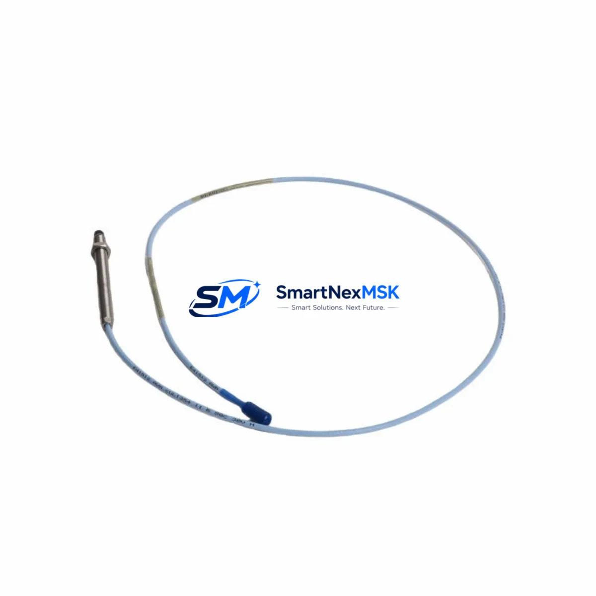
The Bently Nevada 330104-00-15-10-02-CN is an 8mm proximity transducer engineered for the 3300 XL Series vibration monitoring platform. As original equipment reaches end-of-life or becomes increasingly difficult to source through OEM channels, this unit serves as a verified retrofit-ready replacement for facilities operating legacy rotating machinery protection systems. Whether you are upgrading a turbine control cabinet, replacing a failed channel in a compressor monitoring rack, or migrating from an older 3300 Series configuration to the 3300 XL architecture, the 330104-00-15-10-02-CN provides a direct, low-disruption path forward.
This transducer operates within the standard Bently Nevada proximity system signal chain, interfacing with the 3300 XL proximitor/seismic monitor and compatible extension cables. Its 8mm tip diameter, 5-metre integral cable, and -24 VDC bias voltage output align with the electrical and mechanical specifications required for drop-in installation in existing transducer mounts without modification to the machinery casing or bearing housing.
Upgrade Compatibility Table
| Parameter | 330104-00-15-10-02-CN | Retrofit Notes |
|---|---|---|
| Tip Diameter | 8 mm | Direct fit for standard 3300 XL transducer mounts |
| Cable Length | 5 m (integral) | Verify extension cable length; use 330130-045-00-CN if extension required |
| Bias Voltage Output | -24 VDC nominal | Compatible with 3300 XL proximitor input range |
| Sensitivity | 7.87 V/mm (200 mV/mil) | Matches standard 3300 XL channel calibration |
| Frequency Range | DC to 10 kHz | Suitable for shaft vibration and position measurement |
| Installation Interface | M10 x 1 threaded body | No housing modification required for standard mounts |
| Monitor Compatibility | 3300 XL 11/16 Proximitor Monitor | Confirm rack slot assignment and channel address in System 1 software |
| Communication Protocol | Analogue (4–20 mA / voltage) | No protocol migration required; signal wiring unchanged |
| Replacement Relationship | Supersedes 330104-00-15-10-00-CN | Verify suffix compatibility with existing proximitor firmware |
| Warranty | 12 Months | Covered from date of shipment; includes functional verification test report |
Retrofit Planning for Existing Automation Systems
Successful integration of the 330104-00-15-10-02-CN into a running plant begins well before the transducer arrives on site. Engineers should start by auditing the existing 3300 XL rack configuration, confirming the slot assignments of the 3300 XL 11/16 Proximitor Monitor cards and verifying that the associated extension cables — typically the 330130-045-00-CN or 330130-080-00-CN depending on the distance between the machinery and the monitor rack — are within specification and free of insulation damage.
Power supply integrity is a critical pre-installation check. The 3300 XL system draws regulated -24 VDC from the rack power supply module. Before replacing the transducer, confirm that the power supply output is within tolerance and that no other channels on the same supply rail are drawing excess current due to cable faults or failed proximitors. A degraded power supply module can cause the replacement transducer to report erratic gap voltage readings even when the transducer itself is functioning correctly.
Terminal wiring should be documented before disconnection. The 330104-00-15-10-02-CN uses a standard three-conductor connection: power, common, and output. Cross-reference the existing wiring against the 3300 XL installation drawing for the specific rack and channel. If the control cabinet also houses a 3500/42M Proximitor/Seismic Monitor or a 3500/22M Transient Data Interface, confirm that the channel mapping in the Bently Nevada System 1 condition monitoring software reflects the new transducer’s serial number and calibration data.
For facilities running a mixed architecture — for example, where older 3300 Series monitors share a cabinet with newer 3500 Series rack components — the retrofit plan must account for backplane interface differences. The 3300 XL uses a dedicated backplane that is not electrically compatible with the 3500 Series I/O modules. If the long-term roadmap includes migration to the 3500 platform, this transducer replacement is an appropriate interim step that maintains monitoring continuity while the broader system upgrade is planned and budgeted.
HMI screens connected via Modbus or OPC-DA to the System 1 software should be reviewed after installation. Gap voltage, direct vibration, and 1X/2X vector displays tied to the replaced channel will require a baseline reset once the new transducer is gapped and the system is returned to service. Operators should be briefed on the expected gap voltage range (-10 VDC to -18 VDC for standard 8mm transducers at nominal gap) to avoid nuisance alarms during the commissioning window.
Where the retrofit involves replacing multiple transducers across a turbine train — for example, replacing both the radial vibration transducers and the axial position transducer on a steam turbine — coordinate the installation sequence to minimise the number of monitor channels simultaneously in bypass. The 3300 XL Keyphasor Module, if present, should remain active throughout the replacement sequence to preserve phase reference data for vector analysis.
Downtime Control During System Migration
Minimising unplanned downtime during a transducer retrofit requires a structured pre-outage preparation protocol. Before the maintenance window opens, the replacement 330104-00-15-10-02-CN should be bench-tested using a Bently Nevada 330180 proximity calibrator or equivalent to confirm sensitivity, bias voltage, and frequency response against the factory calibration certificate supplied with the unit. This pre-installation verification eliminates the risk of installing a transit-damaged component and discovering the fault only after the machinery is back online.
During the outage, the channel should be placed in bypass within the 3300 XL monitor before the transducer is disconnected. This prevents the monitor from generating a danger or alert output based on an open-circuit input during the swap. The bypass state should be logged in the plant’s permit-to-work system and confirmed with the control room operator before work begins.
Original program logic in the DCS or safety instrumented system that processes the vibration channel output — whether via a 4–20 mA analogue input card or a hardwired relay from the monitor’s relay output module — should not require modification for a like-for-like transducer replacement. However, if the retrofit is accompanied by a monitor firmware update or a change in the alert/danger setpoint configuration, the logic engineer should review the cause-and-effect matrix to confirm that no unintended interlock changes have been introduced.
After installation and gapping, the transducer output should be verified at the monitor front panel and in the System 1 software before the bypass is removed. A final walk-down of the terminal cabinet, confirming that all shield grounds are correctly landed and that no conductors are pinched by cable management hardware, completes the commissioning sequence. Total elapsed time for a single-channel replacement by an experienced technician, including pre-installation testing and post-installation verification, is typically two to four hours.
Retrofit Support FAQ
Q: Is the 330104-00-15-10-02-CN a direct replacement for the 330104-00-15-10-00-CN?
A: Yes. The -02 suffix revision is backward-compatible with the -00 suffix in standard 3300 XL applications. The mechanical dimensions, thread specification, cable length, and electrical output are identical. Confirm the proximitor firmware version supports the -02 suffix if your system uses automated transducer identification features.
Q: What commissioning checks are required after installation?
A: Gap the transducer to the manufacturer-recommended nominal gap (typically 1.0–1.5 mm for 8mm transducers), verify bias voltage at the monitor terminal (expected -10 VDC to -18 VDC), confirm the direct vibration reading is within baseline range on the System 1 display, and reset the OK relay before removing the channel from bypass. Document the as-left gap voltage in the maintenance record.
Q: Can this transducer be used with a 3500 Series monitor rack?
A: The 330104-00-15-10-02-CN is designed and calibrated for the 3300 XL proximitor. While the electrical output is nominally compatible with 3500 Series Proximitor Monitor inputs, Bently Nevada recommends using transducers from the 330100 series that are specifically listed for 3500 Series applications. For 3500 platform migrations, consult the 3500/42M compatibility matrix.
Q: What does the 12-month warranty cover?
A: The warranty covers manufacturing defects and functional performance against the published specification for 12 months from the date of shipment. Each unit is shipped with a functional verification test report. Warranty claims are processed via sales@smartnexmsk.com with the original order reference and a description of the observed fault.
© 2026 SMARTNEXMSK. All rights reserved.
Original Source: https://smartnexmsk.com
Contact: sales@smartnexmsk.com | +86 18259474341


