Bently Nevada 330104-00-16-05-01-CN Retrofit-Ready Proximity Transducer for 3300 XL Control Systems
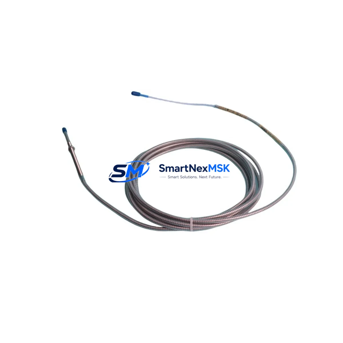
The Bently Nevada 330104-00-16-05-01-CN is an 8mm eddy-current proximity transducer engineered for seamless integration into legacy 3300 XL vibration monitoring systems. As industrial facilities face increasing pressure to extend the operational life of existing machinery protection infrastructure, this transducer serves as a verified drop-in replacement for discontinued or end-of-life sensing components within the 3300 XL platform. Whether you are managing a planned outage, responding to an unplanned sensor failure, or executing a phased control system upgrade, the 330104-00-16-05-01-CN delivers the dimensional accuracy, output linearity, and signal conditioning compatibility required to restore full system functionality with minimal engineering intervention.
This transducer is designed to work within the complete 3300 XL measurement chain. In a typical retrofit scenario, the 330104-00-16-05-01-CN is paired with a compatible extension cable — such as the Bently Nevada 330130-045-00-00 — and a proximitor/oscillator module, commonly the 3300 XL 8mm Proximitor 330180-X1-05. Together, these three components form the sensing loop that feeds conditioned -24 VDC gap voltage signals into the 3300 XL monitor rack. Before installation, engineers must verify that the existing proximitor module is calibrated for the correct gap range and that the target material (typically AISI 4140 steel) matches the transducer’s calibration standard. Deviations in target material conductivity will affect the output scale factor and must be corrected through field calibration or software compensation within the System 1 condition monitoring platform.
Upgrade Compatibility Table
| Parameter | 330104-00-16-05-01-CN | Notes |
|---|---|---|
| Series Compatibility | Bently Nevada 3300 XL | Direct replacement for 3300 XL 8mm transducer assemblies |
| Probe Diameter | 8mm | Matches standard 3300 XL mounting thread (M10 x 1) |
| Cable Length | 5m integral cable | Verify extension cable length for total system reach |
| Output Signal | -24 VDC nominal gap voltage | Compatible with 330180 Proximitor input range |
| Communication Compatibility | Analog (4–20 mA via monitor) | Interfaces with 3300 XL monitor racks and System 1 software |
| Installation Requirement | M10 x 1 threaded boss | Confirm existing mounting boss condition before installation |
| Replacement Recommendation | Direct swap; recalibrate gap after installation | Target gap: 1.0–1.5 mm typical; verify per OEM spec |
| Commissioning Focus | Gap voltage, scale factor, OK relay status | Confirm OK LED on proximitor module after power-up |
| Warranty | 12 Months | Covers manufacturing defects; includes pre-shipment functional test |
Retrofit Planning for Existing Automation Systems
Successful integration of the 330104-00-16-05-01-CN into an operating plant environment requires a structured approach to retrofit planning. The first step is a full audit of the existing 3300 XL monitor rack configuration. This includes identifying the monitor module type — such as the 3300/16 Dual Voting or 3300/20 Radial Vibration Monitor — and confirming that the channel assignment, alert setpoints, and danger setpoints are documented before any hardware is disturbed. The rack’s power supply module, typically a 3300/05 or equivalent, should be load-tested to confirm it can support the replacement transducer’s quiescent current draw without voltage droop on the -24 VDC rail.
Wiring adaptation is a critical checkpoint. The 330104-00-16-05-01-CN uses a standard Bently Nevada coaxial connector at the proximitor end. If the existing installation uses an older integral cable assembly with a different connector style, a field-fabricated adapter or a replacement extension cable — such as the 330130-080-00-00 for longer runs — may be required. All shield terminations must be verified at the junction box and at the monitor rack terminal block to prevent ground loops that would introduce noise into the vibration signal chain.
For facilities running System 1 Evolution software, the channel configuration database should be backed up before the transducer swap. After installation, the new transducer’s serial number and calibration data should be entered into the System 1 asset database to maintain traceability. If the plant also operates a DCS — for example, a Honeywell Experion PKS or an Emerson DeltaV system — the 4–20 mA output from the 3300 XL monitor rack that feeds the DCS analog input card should be verified for correct scaling after the transducer replacement. Any HMI faceplate that displays shaft vibration in engineering units should be checked to confirm the display range and alarm thresholds remain consistent with the recalibrated transducer output.
In multi-machine trains where several 330104-series transducers are installed — for example, on a compressor train with a driver, gearbox, and driven equipment — it is advisable to replace all transducers of the same age cohort during the same planned outage window. This approach avoids repeat outages and ensures uniform signal quality across the entire measurement chain. Spare proximitor modules, extension cables, and a calibration target block should be staged in the control room before work begins.
Downtime Control During System Migration
Minimizing unplanned downtime is the primary operational concern when replacing proximity transducers in a live machinery protection system. The recommended approach is to pre-configure and bench-test the replacement 330104-00-16-05-01-CN assembly — including the extension cable and proximitor — before the machine is taken offline. Using a calibration fixture with a known target material, technicians can verify the gap voltage curve and confirm the OK relay operates correctly at the specified gap range. This pre-shipment functional test, which is performed on every unit we supply, significantly reduces the risk of discovering a configuration issue after the machine has been shut down.
During the actual swap, the 3300 XL monitor channel should be placed in bypass mode — using the front-panel bypass switch or the System 1 software bypass command — to prevent a spurious danger trip while the transducer is disconnected. The original program logic in the safety system or DCS interlock should not be modified during this procedure. Once the new transducer is installed and the gap is set, the bypass should be released only after the OK LED on the proximitor module is confirmed and the gap voltage reading in System 1 is within the acceptable window. This sequence protects the original control logic and maintains field control continuity throughout the replacement process.
For facilities with redundant measurement channels — such as XY proximity probe pairs on journal bearings — the replacement can often be performed on one channel at a time while the redundant channel remains in service, further reducing the risk of a protective trip during maintenance.
Retrofit Support FAQ
Q: Is the 330104-00-16-05-01-CN a direct replacement for other 330104 suffix variants?
A: The 330104 series uses a suffix code to specify cable length, connector type, and approval markings. The -00-16-05-01-CN suffix indicates a 5-meter cable, standard connector, and China market approval. It is dimensionally and electrically compatible with other 330104 variants of the same probe diameter, but you should confirm the cable length and connector type match your installation before ordering.
Q: What commissioning steps are required after installation?
A: After mechanical installation, set the probe gap to the OEM-specified value (typically 1.0–1.5 mm for 8mm probes on steel targets). Power up the proximitor and confirm the OK LED is illuminated. Measure the gap voltage at the monitor terminal block and compare it to the calibration curve. Enter the transducer serial number into System 1 and verify that the channel displays the correct vibration amplitude in engineering units. Release the bypass and confirm alarm and danger setpoints are active.
Q: Can this transducer be used with non-Bently Nevada monitor racks?
A: The 330104-00-16-05-01-CN is optimized for use with Bently Nevada 3300 XL proximitor modules and monitor racks. Use with third-party monitors is possible if the monitor accepts a -24 VDC gap voltage input with the standard Bently Nevada scale factor (200 mV/mil or 7.87 V/mm), but compatibility must be verified by the system integrator.
Q: What does the 12-month warranty cover?
A: The 12-month warranty covers manufacturing defects in materials and workmanship. Every unit undergoes a pre-shipment functional test including gap voltage linearity verification and OK relay operation check. Warranty claims are supported by our technical team with replacement or repair at no charge for confirmed manufacturing defects within the warranty period.
© 2026 SMARTNEXMSK. All rights reserved.
Original Source: https://smartnexmsk.com
Contact: sales@smartnexmsk.com | +86 18259474341


