Bently Nevada 330104-00-16-10-01-CN Maintenance-Ready Spare for 3300 XL Automation
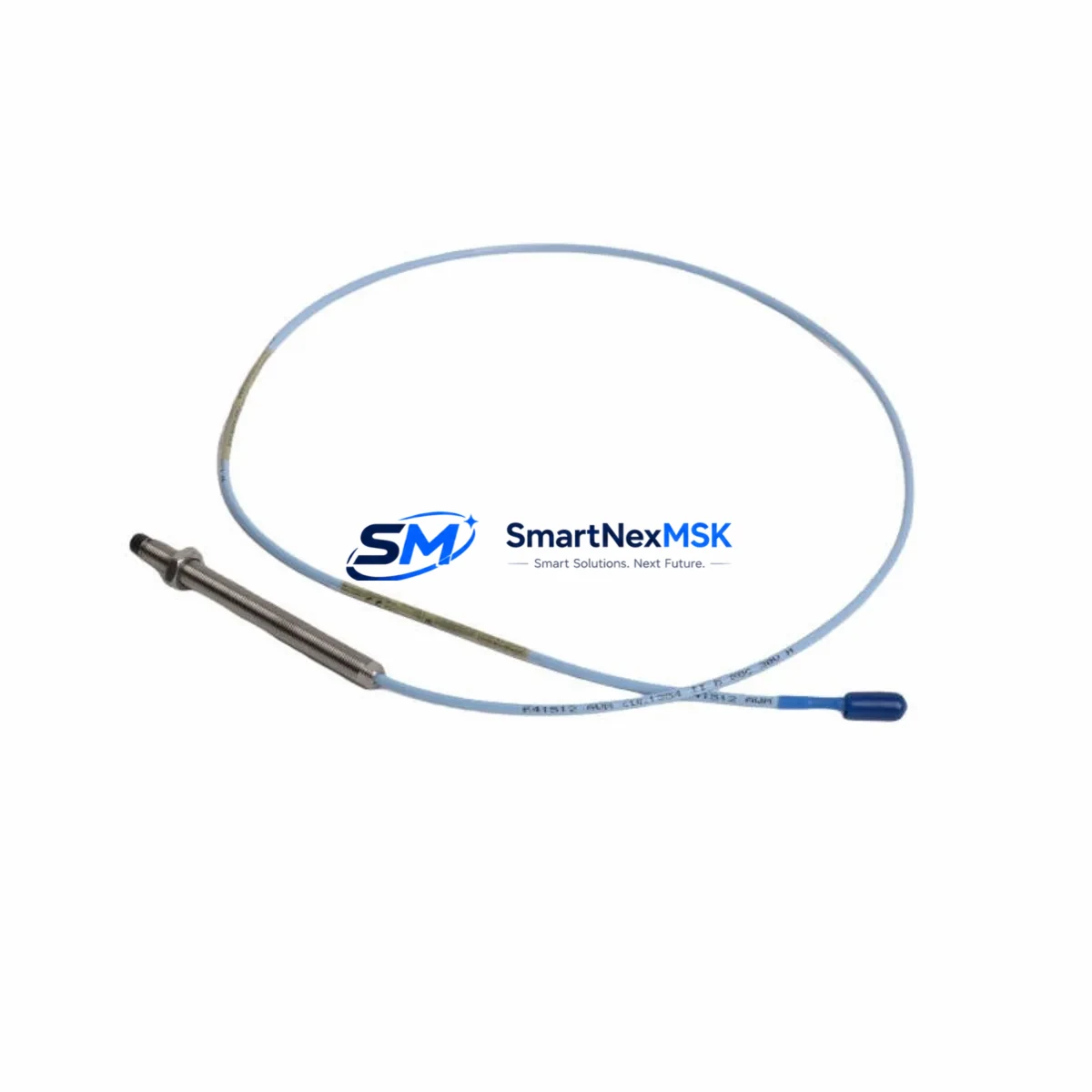
The Bently Nevada 330104-00-16-10-01-CN is an original 8mm proximity transducer engineered for the 3300 XL Series continuous vibration monitoring system. In rotating machinery protection environments — turbines, compressors, pumps, and gearboxes — this transducer is a front-line component in shaft vibration and radial position measurement. When this part fails or degrades, the entire vibration monitoring loop is compromised, triggering unplanned shutdowns and exposing critical rotating assets to undetected mechanical faults.
For maintenance engineers managing aging DCS or PLC-integrated machinery protection systems, having a verified, tested replacement unit on the shelf is not optional — it is a core element of any credible predictive maintenance strategy. The 330104-00-16-10-01-CN is a direct, drop-in replacement for worn or failed transducers in the 3300 XL ecosystem, with no firmware changes or recalibration of the monitoring rack required when replacing like-for-like.
This unit ships tested, with full 12-month warranty coverage, and is sourced to meet the original Bently Nevada specification. Each unit undergoes pre-shipment functional verification to confirm output linearity, gap voltage response, and cable integrity before dispatch.
Spare Maintenance Table
| Parameter | Specification |
|---|---|
| Part Number | 330104-00-16-10-01-CN |
| Brand | Bently Nevada |
| Series | 3300 XL |
| Type | Proximity Transducer (Eddy Current) |
| Probe Diameter | 8mm |
| Cable Length | 1.0m (integral cable) |
| Extension Cable | 330130 Series compatible |
| Driver / Oscillator | 3300 XL 8mm Proximitor® (330180 Series) |
| Supply Voltage | -24 VDC (nominal) |
| Output Range | -2 VDC to -18 VDC |
| Scale Factor | 7.87 V/mm (200 mV/mil) |
| Linear Range | 0.25mm to 2.25mm (10 to 90 mil) |
| Operating Temperature | -35°C to +177°C |
| Connector Type | CN (Integral Connector) |
| Compatibility | 3300 XL monitoring racks, 3500 Series (with adapter), TDXnet systems |
| Application | Radial vibration, axial position, differential expansion, eccentricity |
| Installation | Threaded probe mount, standard 3300 XL bracket |
| Origin | USA |
| Warranty | 12 Months from shipment date |
| Condition | Original spare, pre-shipment tested |
Maintenance Planning for Continuous Operation
When replacing the 330104-00-16-10-01-CN in the field, a disciplined maintenance engineer will not stop at the transducer alone. The 3300 XL measurement chain is a system — and a fault in any link can produce the same symptom: erratic or lost vibration signal. Before closing the work order, the following components in the same electrical loop and control cabinet should be inspected or replaced as part of the same planned outage.
The 330130 Series extension cable runs between the probe and the Proximitor® sensor. Cable damage, connector corrosion, or impedance mismatch is a leading cause of transducer-related alarms that are incorrectly attributed to the probe itself. Inspect the full cable run and replace if shielding is compromised. The 330180 Series 3300 XL 8mm Proximitor® sensor is the oscillator-demodulator that powers the probe and converts gap distance to a DC voltage signal — if the transducer replacement does not resolve the fault, the Proximitor® is the next logical suspect.
At the rack level, the 3300/16 16-channel I/O module and associated 3300/20 rack power supply should be checked for output voltage stability. A sagging -24 VDC supply will cause the entire transducer channel to read incorrectly. If the plant runs a 3500 Series machinery protection rack in parallel or as a migration target, verify that the 3500/42M or 3500/44M I/O modules are configured for the correct transducer type and scale factor before commissioning the replacement probe.
For plants integrating vibration data into a DCS or safety system, the signal isolator or barrier between the Proximitor® output and the DCS analog input card deserves attention — particularly in hazardous area installations where Zener barriers or galvanic isolators are used. A degraded barrier can introduce offset errors that persist even after a clean transducer replacement. Similarly, the terminal blocks and field wiring in the junction box should be torqued and inspected for oxidation, especially in high-humidity or offshore environments.
If the plant uses a TDXnet or System 1 condition monitoring platform connected to the 3300 XL rack, confirm that the channel configuration, alert setpoints, and danger setpoints are correctly restored after the replacement — these are not automatically preserved during a transducer swap. Finally, if this replacement is part of a broader control cabinet refurbishment, consider scheduling inspection of the 3300 XL keyphasor module and any associated relay output modules that drive shutdown logic, as these components share the same rack environment and maintenance window.
Site Replacement Workflow
Step 1 — Isolation and permit: Obtain a valid work permit. Isolate the monitoring channel at the rack (do not de-energize the full rack if other channels are live and protecting running machinery). Note the current gap voltage reading before disconnection — this is your baseline for the new probe setup.
Step 2 — Probe removal: Disconnect the extension cable at the junction box. Unthread the probe from the bracket. Inspect the probe tip and target area for contamination, scoring, or mechanical damage that may indicate a bearing or shaft problem beyond the transducer itself.
Step 3 — New probe installation: Thread the 330104-00-16-10-01-CN into the bracket. Set the initial gap to the midpoint of the linear range (approximately 1.0–1.27mm / 40–50 mil) using a non-ferrous feeler gauge. Reconnect the extension cable. Verify the gap voltage at the Proximitor® output — target approximately -10 VDC at mid-gap for a correctly functioning system.
Step 4 — System verification: Re-enable the monitoring channel. Confirm that the vibration reading is within expected baseline for the machine at rest and at running speed. Clear any latched alarms only after confirming a stable, plausible signal. Document the as-found and as-left gap voltage in the maintenance record.
Step 5 — Spare stock update: Log the consumed unit and trigger a replenishment order to maintain minimum spare holding. For critical rotating machinery, a minimum of one spare transducer, one extension cable, and one Proximitor® sensor per machine train is the recommended inventory posture.
Spare Parts Support FAQ
Q: Is the 330104-00-16-10-01-CN a direct replacement for other 330104 variants?
A: The 330104 family shares the same 8mm eddy current probe design, but suffix codes define cable length, connector type, and temperature rating. The -00-16-10-01-CN variant specifies a 1.0m cable with CN integral connector. Confirm suffix compatibility with your Proximitor® model before ordering. Cross-reference with the 330104-00-16-10-02-CN (2.0m cable) if a longer cable run is required.
Q: How is each unit tested before shipment?
A: Every 330104-00-16-10-01-CN unit is bench-tested against a calibrated 3300 XL Proximitor® sensor prior to dispatch. Output linearity across the full gap range, scale factor accuracy, and cable continuity are verified. A test report is available on request. Units that do not meet original Bently Nevada specification are not shipped.
Q: What does the 12-month warranty cover?
A: The 12-month warranty covers manufacturing defects, output failure, and cable integrity from the date of shipment. It does not cover damage resulting from incorrect installation, mechanical impact, or operation outside the specified temperature and voltage range. Warranty claims are processed with return of the defective unit and a completed fault description form.
Q: Can this part be used in a 3500 Series rack?
A: The 330104-00-16-10-01-CN is natively compatible with the 3300 XL Proximitor® ecosystem. Use in a 3500 Series rack requires a compatible 3500/42M or 3500/44M I/O module configured for 8mm transducer input. Consult the 3500 rack configuration guide and verify scale factor settings before commissioning. Contact our technical team for compatibility confirmation specific to your rack revision.
© 2026 SMARTNEXMSK. All rights reserved.
Original Source: https://smartnexmsk.com
Contact: sales@smartnexmsk.com | +86 18259474341


