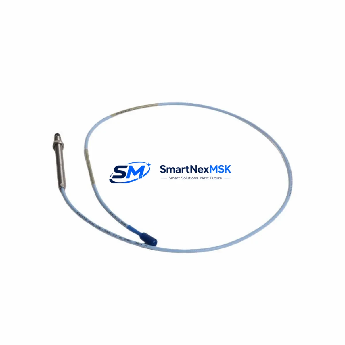
Bently Nevada 330104-00-18-10-01-CN Retrofit-Ready Proximity Transducer for 3300 XL Control Systems
The Bently Nevada 330104-00-18-10-01-CN is an 18mm eddy current proximity transducer engineered for seamless integration into existing 3300 XL vibration monitoring systems. As legacy machinery monitoring infrastructure ages and OEM support for older Bently Nevada 3300 series components becomes increasingly limited, plant engineers and reliability teams face mounting pressure to source verified drop-in replacements that preserve system integrity without requiring full platform migration. This unit addresses that need directly — offering a retrofit-ready solution that maintains signal chain continuity, dimensional compatibility, and calibration alignment with the original 3300 XL architecture.
Whether you are replacing a failed transducer on a critical rotating machine, upgrading a control cabinet that still runs on a 3300 XL rack, or consolidating spare parts inventory ahead of a planned outage, the 330104-00-18-10-01-CN delivers the electrical and mechanical specifications required for a reliable, low-risk swap. The transducer is compatible with the standard Bently Nevada 3300 XL proximitor/seismic monitor and integrates directly with the 3300/16 and 3300/20 monitor modules without firmware changes or signal conditioning modifications.
Before installation, engineers should verify the following parameters against the existing system configuration: supply voltage to the proximitor (typically –24 VDC), cable length and extension cable type (matched to the 330130 series extension cables), gap voltage at the target surface (nominally –10.0 VDC at 1.0 mm gap for 18mm probes), and the sensitivity factor (7.87 V/mm standard). Confirm that the existing Bently Nevada 3500/42M or 3300/16 monitor card is configured for the correct transducer type and gap range before powering the loop.
Upgrade Compatibility Table
| Parameter | 330104-00-18-10-01-CN (This Unit) | Notes / Retrofit Guidance |
|---|---|---|
| Probe Diameter | 18 mm | Direct fit for 3300 XL 18mm probe holders |
| Cable Length | 1.0 m (integral) | Pair with 330130-045-00-00 extension cable as needed |
| Sensitivity | 7.87 V/mm (200 mV/mil) | Matches 3300 XL monitor card calibration |
| Supply Voltage | –24 VDC nominal | Verify proximitor power rail before swap |
| Gap Voltage (1.0 mm) | –10.0 VDC ±0.5 V | Re-gap after installation; record baseline |
| Target Material | AISI 4140 steel (standard) | Confirm target material; adjust gap for non-standard alloys |
| Monitor Compatibility | 3300/16, 3300/20, 3500/42M | No firmware change required |
| Communication Protocol | Analog (4–20 mA / voltage) | Compatible with existing DCS analog input cards |
| Installation Thread | M18 × 1.5 | Standard 3300 XL probe holder thread |
| Warranty | 12 Months | Covers manufacturing defects; includes pre-ship functional test |
Retrofit Planning for Existing Automation Systems
Successful retrofit of the 330104-00-18-10-01-CN into a legacy 3300 XL monitoring loop requires a structured approach that accounts for the full signal chain — from the probe tip through the extension cable, proximitor, monitor card, and ultimately to the DCS or safety system receiving the vibration signal.
Begin by auditing the existing rack configuration. A typical 3300 XL installation includes a 3300/05 power supply module, one or more 3300/16 or 3300/20 monitor cards, and a 3300/55 or 3300/60 communication gateway for Modbus RTU or FOUNDATION Fieldbus output to the plant DCS. Confirm that the power supply module has sufficient capacity to support the replacement transducer’s current draw alongside existing channel loads — the 3300/05 is rated for a fixed number of monitor cards, and adding channels without verifying headroom can cause intermittent supply dropout.
Next, inspect the extension cable routing. The 330130 series extension cables are the standard interconnect between the probe and the proximitor. If the existing cable shows signs of jacket degradation, connector corrosion, or impedance drift (measurable with a cable tester against the 330130 specification sheet), replace it concurrently with the probe to avoid masking a cable fault behind a new transducer. Mixing cable lengths outside the matched system specification will shift the gap voltage curve and introduce calibration error.
For installations where the 3300 XL rack communicates with a Honeywell DeltaV, Emerson Ovation, or ABB 800xA DCS via a 3300/55 Modbus gateway, verify that the channel address mapping in the gateway configuration matches the physical slot assignment of the replacement monitor card. A mismatch here will cause the DCS historian to log data against the wrong tag, which can corrupt trend records and trigger false maintenance alerts.
If the plant is also upgrading adjacent I/O — for example, replacing a legacy 3300/20 monitor with a newer 3500/42M proximitor monitor — note that the 3500 series uses a different rack backplane and requires a 3500/05 power supply rather than the 3300/05. Plan the backplane and rack upgrade as a coordinated activity to avoid mixed-generation hardware in the same chassis. The 3500/42M supports both the 330104 series probes and the newer 330180 series, giving you a forward-compatible platform for future transducer standardization.
HMI screen updates are often overlooked during transducer retrofits. If the plant SCADA or HMI (such as a Wonderware InTouch or Ignition-based system) displays gap voltage or vibration amplitude from the 3300 XL channel, verify that the engineering unit scaling and alarm setpoints on the HMI faceplate match the new transducer’s sensitivity curve. A 7.87 V/mm sensitivity factor should already be configured if the original probe was a standard 3300 XL 18mm unit, but confirm this against the HMI tag database before returning the loop to service.
Downtime Control During System Migration
Minimizing unplanned downtime during a proximity transducer swap on a critical rotating machine requires pre-staging all replacement components, verifying compatibility offline, and executing the physical swap within a defined maintenance window — ideally during a scheduled outage or a planned load reduction period.
Before the maintenance window opens, bench-test the 330104-00-18-10-01-CN against a reference target at the specified gap distance and confirm the output voltage falls within the –10.0 VDC ±0.5 V tolerance. Document the as-found gap voltage of the existing probe before removal — this baseline allows you to set the replacement probe to the same gap without iterative adjustment, reducing commissioning time at the machine.
If the machine cannot be taken offline, consider a hot-standby approach where the replacement transducer is pre-gapped in a bench fixture and the monitor card is configured in bypass mode during the swap interval. Most 3300/16 and 3300/20 monitor cards support a maintenance bypass that suppresses the alarm output without disabling the channel, allowing the swap to proceed without triggering a plant-wide shutdown interlock.
After installation, perform a slow-roll vibration check at reduced machine speed to verify that the new transducer tracks shaft motion correctly before returning to full operating speed. Log the gap voltage, DC output, and peak-to-peak vibration reading in the maintenance record alongside the transducer serial number and installation date. This documentation supports the 12-month warranty claim process and provides a calibration baseline for the next scheduled inspection.
All units supplied by SMARTNEXMSK undergo a pre-shipment functional test against a calibrated reference target. Test records are available upon request and can be included with the shipment documentation for quality assurance purposes.
Retrofit Support FAQ
Q: Is the 330104-00-18-10-01-CN a direct drop-in replacement for the original Bently Nevada part?
A: Yes. This unit is manufactured to the same dimensional, electrical, and sensitivity specifications as the original 330104-00-18-10-01-CN. It is compatible with the 3300 XL monitor system without modification to the monitor card, extension cable, or proximitor configuration. A gap re-check after installation is recommended as standard practice for any transducer replacement.
Q: What extension cable should I use with this transducer?
A: The 330104-00-18-10-01-CN is designed for use with the Bently Nevada 330130 series extension cables. The total system cable length (probe integral cable plus extension) must match the proximitor’s calibrated range. Confirm the extension cable part number against the proximitor label or the original system documentation before ordering.
Q: How do I verify compatibility with my existing 3300/16 or 3500/42M monitor card?
A: Check the monitor card’s configuration label or the rack documentation for the transducer type and sensitivity setting. The 330104-00-18-10-01-CN uses the standard 7.87 V/mm (200 mV/mil) sensitivity, which is the default calibration for 3300 XL 18mm systems. If the monitor card was previously configured for a different sensitivity (e.g., for a 5mm or 8mm probe), recalibration is required before the replacement transducer will read correctly.
Q: What does the 12-month warranty cover, and how is a claim initiated?
A: The 12-month warranty covers manufacturing defects in materials and workmanship from the date of shipment. It does not cover damage resulting from incorrect installation, overvoltage, mechanical impact, or use outside the specified operating environment. To initiate a warranty claim, contact SMARTNEXMSK with the order number, transducer serial number, and a description of the fault. A replacement unit or repair will be arranged within the warranty terms.
© 2026 SMARTNEXMSK. All rights reserved.
Original Source: https://smartnexmsk.com
Contact: sales@smartnexmsk.com | +86 18259474341


