Bently Nevada 330104-00-19-50-02-00: Retrofit-Ready Proximity Probe for 3300 XL Control Systems
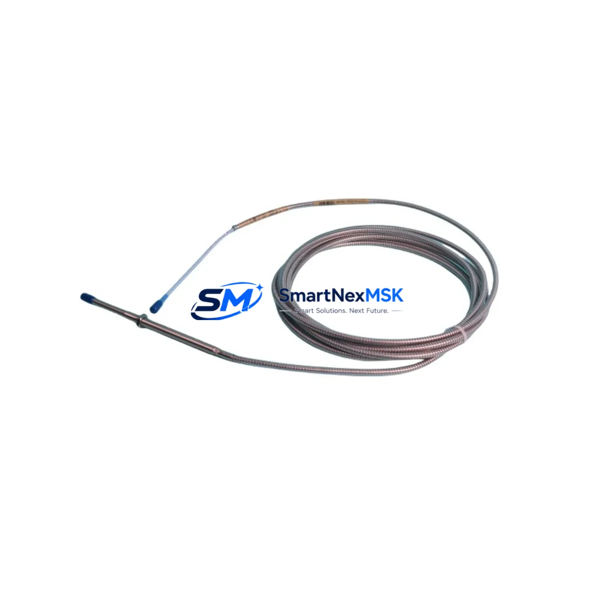
The Bently Nevada 330104-00-19-50-02-00 is an 8mm eddy current proximity probe engineered for continuous vibration and position monitoring in rotating machinery applications. Designed as a retrofit-ready replacement for legacy 3300 XL Series monitoring systems, this probe delivers the same signal conditioning characteristics, gap voltage linearity, and sensitivity specifications as the original factory component — enabling seamless integration into existing control architectures without reprogramming the monitor or recalibrating the entire measurement chain.
Industrial facilities operating turbines, compressors, pumps, and gearboxes that were originally commissioned with Bently Nevada 3300 XL monitors frequently encounter the challenge of sourcing discontinued or long-lead-time proximity probes. The 330104-00-19-50-02-00 addresses this directly: it maintains the standard 5-metre integral cable configuration, the -24 VDC driver supply compatibility, and the 200 mV/mil (7.87 V/mm) sensitivity required by the 3300 XL Proximitor® sensor ecosystem. When paired with the 330180 or 330130 series Proximitor® extension cables and the 3300 XL 8mm Proximitor® sensor, the measurement loop remains fully validated without requiring new loop calibration records.
Before installing this probe in a retrofit or upgrade scenario, engineers should verify the following parameters against the existing installation: power supply rail voltage at the I/O terminal block, cable routing clearance within the control cabinet, and the gap voltage setpoint stored in the 3500/40M or 3500/42M monitor module. If the plant is migrating from an older 3300/16 or 3300/20 monitor frame to the current 3500 Series rack, the probe itself is mechanically and electrically compatible, but the monitor channel configuration — including alert and danger setpoints, full-scale range, and OK relay logic — must be re-entered in the 3500 Rack Configuration Software before commissioning.
For control cabinets undergoing a broader modernization, the 330104-00-19-50-02-00 is commonly deployed alongside the 3500/22M Transient Data Interface, the 3500/32 4-Channel Relay Module, and the 3500/92 Communication Gateway to complete a full vibration monitoring upgrade. Plants integrating Modbus RTU or Ethernet/IP communication into their DCS or SCADA layer will find that the 3500/92 gateway bridges the 3300 XL probe signal chain into modern protocol environments without replacing field wiring.
Upgrade Compatibility Table
| Parameter | Specification / Recommendation |
|---|---|
| Probe Type | 8mm Eddy Current Proximity Probe |
| Sensitivity | 200 mV/mil (7.87 V/mm) |
| Driver Supply Voltage | -24 VDC (compatible with 3300 XL Proximitor® sensor) |
| Cable Length | 5 metres integral cable (standard) |
| Connector Interface | Standard BNC / coaxial — compatible with 330130 / 330180 extension cables |
| Monitor Compatibility | 3300 XL, 3500/40M, 3500/42M, 3500/45, 3500/46M |
| Communication Protocol | Analog signal; gateway integration via 3500/92 for Modbus RTU / Ethernet/IP |
| Replacement for | 3300/16, 3300/20 legacy probe assemblies; discontinued 330104 variants |
| Installation Requirement | Verify gap voltage, OK relay setpoint, and channel configuration before energizing |
| Commissioning Note | Re-enter alert/danger setpoints in 3500 Rack Configuration Software if migrating monitor frame |
| Warranty | 12-Month Warranty — covers manufacturing defects and signal performance |
Retrofit Planning for Existing Automation Systems
A successful retrofit begins well before the maintenance window opens. The first step is a full audit of the existing probe-to-monitor signal chain: confirm that the 3300 XL Proximitor® sensor housing is undamaged, that the 330130 or 330180 extension cable shows no shield continuity faults, and that the terminal block wiring in the junction box matches the original loop drawing. If the plant is also upgrading the monitor rack from a 3300 Series frame to a 3500 Series chassis, the I/O module — typically a 3500/40M Proximitor®/Seismic Monitor or a 3500/42M Proximitor®/Seismic Monitor — must be configured before the new probe is installed.
In multi-channel installations, it is common to replace the 330104-00-19-50-02-00 probe while simultaneously upgrading the 3500/32 4-Channel Relay Module to ensure that the OK relay and danger relay outputs are correctly mapped to the new channel assignments. Plants running a Bently Nevada System 1 condition monitoring platform should also update the device database to reflect the new probe serial number and calibration date, ensuring that trend data continuity is maintained across the retrofit boundary.
For facilities that are expanding I/O capacity as part of the upgrade — for example, adding radial vibration monitoring to a previously unmonitored bearing — the 3500 rack can accommodate additional 3500/40M or 3500/42M modules in the same backplane without requiring a new rack or power supply, provided the 3500/15 Power Supply Module has sufficient headroom. Always verify the total current draw against the power supply rating before adding modules. The 3500/20 Rack Interface Module handles backplane communication and should be checked for firmware compatibility with any newly added I/O modules.
If the retrofit scope includes HMI updates, the Bently Nevada System 1 software or the plant’s existing SCADA display pages will need to be revised to reflect the new channel tag names, engineering unit labels, and alarm setpoint values. Coordinate with the control room team to schedule a brief display freeze during the cutover to avoid nuisance alarms during the gap voltage stabilization period immediately after probe installation.
Downtime Control During System Migration
Minimizing unplanned downtime during a proximity probe replacement requires a structured pre-outage checklist. Before the maintenance window, pre-configure the replacement 330104-00-19-50-02-00 probe assembly on the bench: measure the static gap voltage at the nominal installation gap (typically 1.0 mm for 8mm probes), confirm the output is within the linear range of the Proximitor® sensor, and document the as-found gap voltage for the maintenance record.
During the outage, follow a defined sequence: isolate the monitor channel using the 3500/40M channel inhibit function to suppress false alarms, remove the existing probe, install the 330104-00-19-50-02-00, set the mechanical gap using a non-ferrous feeler gauge, and reconnect the extension cable. Re-enable the channel only after the gap voltage has stabilized and the OK relay has picked up. This sequence protects the original program logic in the 3500 monitor — no ladder logic or function block changes are required in the PLC or DCS layer, since the probe replacement is transparent to the control system above the monitor level.
For plants where continuous operation is critical, a hot-standby probe arrangement using a dual-probe bracket can reduce the actual signal interruption to under two minutes. Ensure that the 3500/42M channel is configured for dual-probe input mode if this approach is used. After restoration, run a 30-minute trend capture in System 1 or the plant historian to confirm that vibration baseline values are consistent with pre-outage records before releasing the machine to production.
Retrofit Support FAQ
Q1: Is the 330104-00-19-50-02-00 a direct drop-in replacement for older 330104 variants with different suffix codes?
A: The 330104 base part number covers a family of 8mm proximity probes with varying cable lengths and connector configurations indicated by the suffix. The -00-19-50-02-00 suffix specifies a 5-metre integral cable with standard coaxial termination. If your existing installation uses a different cable length suffix, the probe body and sensitivity are identical, but you must verify that the total cable length (probe cable + extension cable) falls within the Proximitor® sensor’s specified range — typically 5m, 9m, or 15m total. Mixing suffix variants is acceptable provided the total loop length is within specification.
Q2: Do I need to recalibrate the 3300 XL monitor after installing this replacement probe?
A: A full system recalibration is not required if the replacement probe is the same part number and the mechanical installation gap is set to the original design value. However, you should perform a gap voltage verification and compare the as-left reading against the original commissioning record. If the gap voltage differs by more than ±0.5 VDC from the original value, adjust the probe position and re-verify before re-enabling the channel.
Q3: What is covered under the 12-Month Warranty?
A: The 12-month warranty covers manufacturing defects, signal performance deviations from published sensitivity specifications, and connector integrity. It does not cover damage resulting from incorrect installation gap, reverse polarity wiring, or mechanical impact. Each unit undergoes pre-shipment functional testing — gap voltage linearity, insulation resistance, and cable continuity — and ships with a test report. Warranty claims are processed within 5 business days of receipt of the returned unit.
Q4: Can this probe be used with third-party vibration monitors that accept standard eddy current probe inputs?
A: The 330104-00-19-50-02-00 is optimized for use with Bently Nevada Proximitor® sensors and 3300/3500 Series monitors. It can be used with third-party monitors that accept a -24 VDC powered eddy current probe with 200 mV/mil sensitivity, but compatibility must be verified against the third-party monitor’s input specification. SMARTNEXMSK recommends bench-testing the probe with the target monitor before field installation when using non-Bently Nevada monitor hardware.
© 2026 SMARTNEXMSK. All rights reserved.
Original Source: https://smartnexmsk.com
Contact: sales@smartnexmsk.com | +86 18259474341


