Bently Nevada 330104-00-21-05-01-00 Retrofit-Ready Proximity Transducer for 3300 XL Control Systems
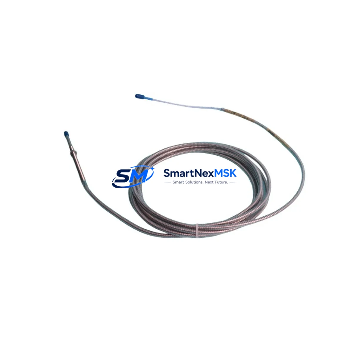
The Bently Nevada 330104-00-21-05-01-00 is an eddy-current proximity transducer engineered for the 3300 XL Series vibration monitoring platform. As legacy 3300 Series installations reach end-of-service milestones, this transducer serves as the primary retrofit solution for facilities upgrading from discontinued 3300/05 and 3300/16 monitor assemblies to the current 3300 XL architecture. With a 5-metre armored extension cable, 8 mm tip diameter, and a standard -24 VDC bias voltage output, the 330104-00-21-05-01-00 integrates directly into existing Bently Nevada rack systems without requiring signal conditioning modifications.
Industrial sites operating rotating machinery — including steam turbines, gas compressors, centrifugal pumps, and gearboxes — rely on this transducer for continuous radial vibration and axial position measurement. When replacing a failed or obsolete 330104-00-05-05-01-00 or 330104-00-10-05-01-00 variant, engineers must verify the extension cable length, tip diameter, and gap voltage range against the existing proximitor/driver specifications. The 330104-00-21-05-01-00 pairs directly with the 3300 XL 8mm Proximitor Sensor (330180-51-05) and is fully compatible with the 3500/42M Proximitor/Seismic Monitor module installed in 3500 Series rack systems.
Upgrade Compatibility Table
| Parameter | 330104-00-21-05-01-00 | Notes / Retrofit Guidance |
|---|---|---|
| Tip Diameter | 8 mm | Confirm bore clearance in existing probe holder |
| Extension Cable Length | 5 m (21 = 5 m code) | Match to existing conduit run; alternatives: 330104-00-10-05-01-00 (2.5 m) |
| Output Bias Voltage | −24 VDC nominal | Verify proximitor driver input range before installation |
| Compatible Proximitor | 330180-51-05 / 330180-91-05 | Replace proximitor if gap voltage out of range |
| Monitor Compatibility | 3300 XL, 3500/42M, 3500/42 | Not compatible with legacy 3300/05 without driver upgrade |
| Communication Protocol | Analog (4–20 mA / voltage) | No protocol migration required; signal wiring unchanged |
| Installation Standard | API 670 compliant | Confirm bracket and target material (steel preferred) |
| Warranty | 12 Months | Covers manufacturing defects; includes pre-shipment functional test |
Retrofit Planning for Existing Automation Systems
A successful retrofit begins well before the maintenance window opens. When migrating from a 3300 Series monitor to a 3300 XL or 3500 Series rack, the first step is auditing the existing probe-to-proximitor wiring harness. The 330104-00-21-05-01-00 uses the same Bently Nevada standard coaxial cable termination as its predecessors, so the junction box connections at the field end typically require no re-termination — a significant advantage in reducing downtime during a planned outage.
The proximitor driver is the component most likely to require replacement during this upgrade. If the existing installation uses an older 3300/16 proximitor, it must be swapped for a 330180-51-05 or 330180-91-05 unit to maintain calibrated gap voltage output within the −17 VDC to −24 VDC operating window. The new proximitor mounts in the same DIN-rail or panel-mount footprint, and its output connects directly to the 3500/42M Proximitor/Seismic Monitor input channel without additional signal conditioning.
For facilities running a 3500 Series rack, the 3500/20 Rack Interface Module (RIM) and 3500/15 Power Supply Module should be inspected for firmware compatibility before commissioning the new transducer. The 3500/15 supplies regulated −24 VDC to the proximitor loop; if the power supply is original to a pre-2005 installation, a capacity verification against the updated channel count is recommended. Similarly, the 3500/92 Communication Gateway Module — if present — should be confirmed at firmware revision 3.x or later to ensure Modbus RTU or FOUNDATION Fieldbus data mapping remains intact after the transducer swap.
I/O mapping in the condition monitoring software (System 1 Evolution or equivalent) must be reviewed before the outage. The channel tag, engineering unit scaling (µm or mil), and alarm setpoints associated with the old transducer should be exported and re-imported against the new channel configuration. If the plant uses a DCS integration — for example, via a 3500/92 gateway feeding a Honeywell Experion or Emerson DeltaV system — the OPC DA or Modbus register map should be validated post-commissioning to confirm that vibration and position values are updating correctly at the DCS historian.
Where the control cabinet houses both the 3500 rack and a separate PLC — such as an Allen-Bradley ControlLogix L73 or Siemens S7-400 — the hardwired relay outputs from the 3500/42M (OK relay, Alert relay, Danger relay) should be re-verified against the PLC input card wiring diagram. Terminal block labeling in the cabinet should be updated to reflect the new transducer tag number, and the as-built drawing package revised accordingly before the system is returned to service.
Downtime Control During System Migration
Minimizing unplanned downtime during a proximity transducer replacement requires a structured pre-outage checklist. Before the machine is taken offline, the replacement 330104-00-21-05-01-00 should be bench-tested against a calibrated target at the nominal air gap (typically 1.0 mm for an 8 mm probe) to confirm output voltage is within specification. This pre-shipment functional test is included with every unit supplied by SMARTNEXMSK and documented on the accompanying test certificate.
During the outage, the original program logic in the 3500/42M — including gap alarm limits, vibration alert thresholds, and danger setpoints — should be recorded from the System 1 software before any hardware is disturbed. This ensures that if the monitor requires a configuration reset during the swap, all setpoints can be restored from the saved record rather than from memory or an outdated commissioning document.
The physical swap itself — removing the old probe from its holder, threading in the replacement, and setting the air gap — typically takes under 30 minutes for an experienced technician. The critical path item is the gap voltage verification: with the machine stationary, the proximitor output should read between −10 VDC and −12 VDC at the nominal 1.0 mm gap. If the reading falls outside this range, the gap must be adjusted before the machine is restarted. Once gap voltage is confirmed, the OK relay in the 3500/42M will energize, and the channel status in System 1 will transition from Not OK to OK, confirming the transducer loop is healthy.
For sites where continuous operation is critical, a spare 330104-00-21-05-01-00 held in the on-site critical spares inventory eliminates the lead-time risk entirely. SMARTNEXMSK maintains in-stock inventory of this transducer and can support same-day dispatch for urgent requirements.
Retrofit Support FAQ
Q1: Is the 330104-00-21-05-01-00 a direct drop-in replacement for the 330104-00-10-05-01-00?
A: The two part numbers differ only in extension cable length (5 m vs. 2.5 m). All electrical specifications — tip diameter, bias voltage, sensitivity, and proximitor compatibility — are identical. If the existing conduit run accommodates the longer cable, the 330104-00-21-05-01-00 is a direct replacement. Excess cable should be coiled and secured inside the junction box rather than cut.
Q2: What commissioning checks are required after installation?
A: After physical installation, verify gap voltage at the proximitor output terminal (target: −10 to −12 VDC at 1.0 mm gap), confirm the OK relay has energized in the 3500/42M, check that System 1 is receiving a valid vibration reading on the channel, and validate that DCS/PLC hardwired relay inputs are reflecting the correct OK/Alert/Danger states. Document the as-found and as-left gap voltage readings in the maintenance record.
Q3: Can this transducer be used with a non-Bently Nevada monitor?
A: The 330104-00-21-05-01-00 is calibrated for use with Bently Nevada proximitor drivers. It can be used with third-party monitors that accept a standard eddy-current probe input, provided the monitor’s driver circuit supplies the correct −24 VDC excitation and is calibrated to the 200 mV/mil (7.87 V/mm) sensitivity curve. Compatibility verification with the third-party monitor manufacturer is recommended before installation.
Q4: What does the 12-month warranty cover, and what is included in the pre-shipment test?
A: The 12-month warranty covers manufacturing defects in materials and workmanship from the date of shipment. Each unit undergoes a pre-shipment functional test that verifies output voltage at a calibrated air gap, cable continuity, and connector integrity. A test certificate is included with the shipment. Warranty claims are supported by SMARTNEXMSK with replacement unit dispatch within 5 business days of confirmed defect verification.
© 2026 SMARTNEXMSK. All rights reserved.
Original Source: https://smartnexmsk.com
Contact: sales@smartnexmsk.com | +86 18259474341


