Bently Nevada 330104-00-23-10-02-CN Retrofit-Ready Proximity Transducer for 3300 XL Control Systems
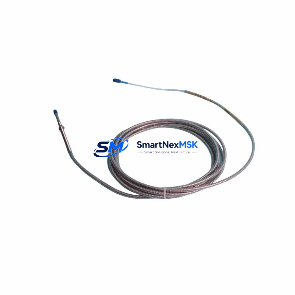
The Bently Nevada 330104-00-23-10-02-CN is an 8mm proximity transducer engineered for seamless integration into legacy 3300 XL vibration monitoring systems. As industrial facilities face increasing pressure to extend the operational life of existing machinery protection infrastructure, this transducer serves as a verified drop-in replacement for discontinued or end-of-life units within the 3300 XL platform. Whether you are executing a planned control system upgrade, recovering from an unplanned equipment failure, or consolidating spare parts inventory ahead of a scheduled shutdown, the 330104-00-23-10-02-CN delivers the signal conditioning performance and mechanical compatibility required to restore full system functionality with minimal engineering effort.
Designed to operate within the Bently Nevada 3300 XL proximity system architecture, this transducer pairs directly with the 330130 extension cable and the 330180 proximitor/oscillator to form a complete eddy-current sensing chain. The system outputs a linear DC voltage proportional to the gap between the probe tip and the observed target surface, making it suitable for radial vibration, axial position, and differential expansion measurements on rotating machinery including steam turbines, gas compressors, centrifugal pumps, and large induction motors.
When planning a retrofit or replacement installation, engineers must verify several critical parameters before energizing the new transducer. Power supply requirements for the 3300 XL proximitor typically call for a regulated -24 VDC supply; confirm that the existing power module — such as the 3300/20 power supply or equivalent rack-mounted unit — can sustain the required current draw after adding or replacing sensing channels. Terminal wiring at the junction box or field terminal assembly must be inspected for correct polarity and shielding continuity, as improper grounding of the coaxial cable shield is a leading cause of signal noise and false vibration alarms during commissioning.
Backplane and rack interface compatibility is equally important. The 3300 XL monitor cards, including the 3300/16 and 3300/25 dual-channel monitors, accept the standard -24 VDC proximitor output and are designed to work with the 330104 series transducer family. If the existing rack also houses 3500 series monitor cards as part of a mixed-generation installation, verify that the channel configuration software — typically managed through System 1 or the 3500 Rack Configuration Utility — correctly identifies the transducer type and gap voltage range to avoid calibration errors.
Module addressing and channel mapping should be confirmed in the rack configuration before the replacement transducer is installed. Incorrect channel assignments can cause the System 1 condition monitoring software to misroute vibration data, leading to erroneous trend plots and missed alarm conditions. If the facility uses a DCS integration layer — for example, a Honeywell Experion PKS or Emerson DeltaV node receiving 4–20 mA or Modbus RTU signals from the 3300 XL rack — verify that the analog output scaling and alarm setpoints remain consistent with the original transducer’s sensitivity specification of 7.87 V/mm (200 mV/mil).
HMI screen updates are often overlooked during transducer replacements. If the control room display is driven by a Wonderware InTouch or FactoryTalk View application, confirm that the tag database references the correct engineering unit conversion for the new channel. Discrepancies between the transducer sensitivity and the HMI scaling factor will produce incorrect vibration amplitude readings, which can mask developing faults or trigger nuisance trips.
Communication link integrity between the 3300 XL rack and the plant historian or condition monitoring server should be validated after installation. RS-232 or Ethernet-based data acquisition paths may require a brief re-synchronization cycle to re-establish the channel handshake. Field commissioning should include a static gap check using a calibrated gap simulator, followed by a dynamic runout verification at operating speed to confirm that the installed transducer meets the original system’s acceptance criteria.
All units supplied by SMARTNEXMSK are subject to pre-shipment functional testing, including gap voltage linearity verification across the full measurement range. Each 330104-00-23-10-02-CN is shipped with a 12-month warranty covering manufacturing defects and signal performance deviations from the published specification. Expedited shipping options are available to support emergency maintenance scenarios where minimizing machinery downtime is the primary operational priority.
Upgrade Compatibility Table
| Parameter | Detail |
|---|---|
| SKU / Part Number | 330104-00-23-10-02-CN |
| Brand / Manufacturer | Bently Nevada |
| Compatible System Series | 3300 XL Proximity System |
| Probe Diameter | 8 mm |
| Sensitivity | 7.87 V/mm (200 mV/mil) |
| Supply Voltage | -24 VDC (via proximitor) |
| Compatible Proximitor | 330180 Proximitor/Oscillator |
| Compatible Extension Cable | 330130 Series |
| Compatible Monitor Cards | 3300/16, 3300/25 Dual-Channel Monitors |
| Installation Type | Direct retrofit — no bracket modification required |
| Communication Compatibility | Analog 4–20 mA, Modbus RTU (via rack interface) |
| Replacement Recommendation | Drop-in replacement for discontinued 330104 series units |
| Commissioning Requirement | Static gap check + dynamic runout verification at speed |
| Warranty | 12 months — manufacturing defects and signal performance |
| Pre-Shipment Testing | Gap voltage linearity verified across full measurement range |
Retrofit Planning for Existing Automation Systems
A successful retrofit of the 330104-00-23-10-02-CN into an operating plant begins with a thorough audit of the existing sensing chain. The complete 3300 XL proximity system consists of three interdependent components: the probe itself, the 330130 extension cable, and the 330180 proximitor/oscillator. If the extension cable shows signs of jacket damage, connector corrosion, or impedance drift, it should be replaced concurrently with the transducer to avoid introducing a new fault source into a freshly commissioned channel.
At the rack level, the 3300/20 power supply module must be confirmed as capable of supporting the full channel load after the replacement. In installations where the rack also hosts 3300/25 dual-channel vibration monitors alongside 3300/50 Keyphasor modules, the aggregate current draw can approach the power module’s rated output. Adding a replacement transducer channel without verifying available headroom risks nuisance power faults during startup.
For facilities that have partially migrated to the 3500 series platform, the 330104-00-23-10-02-CN can continue to serve legacy 3300 XL channels while the 3500/42M and 3500/45 position monitor cards handle upgraded measurement points on the same machinery train. This mixed-generation approach is common in phased modernization programs where full rack replacement is deferred to a future outage window.
Wiring adaptation at the field junction box should account for the coaxial cable’s characteristic impedance. Use only the specified RG-58 or equivalent low-loss coaxial cable for extension runs beyond the standard 330130 cable length. Improper cable substitution is a frequent source of sensitivity deviation that is difficult to diagnose without a calibrated gap simulator.
If the plant’s condition monitoring architecture includes a System 1 server collecting data from multiple 3300 XL racks, the replacement channel should be re-learned by the software after installation. System 1’s channel configuration wizard will prompt the technician to confirm the transducer type, gap voltage at the operating air gap, and alarm setpoints inherited from the previous channel definition. This step ensures that historical trend data remains continuous and that the new channel’s baseline is correctly established for future fault detection.
For facilities using a Bently Nevada TK-3 or TK-81 portable calibrator, a bench verification of the replacement transducer’s gap voltage curve prior to installation is strongly recommended. This pre-installation check confirms that the unit’s sensitivity matches the published specification and provides a documented acceptance record for the maintenance file.
Downtime Control During System Migration
Minimizing machinery downtime during a transducer replacement requires a structured pre-outage preparation protocol. Before the planned maintenance window opens, the replacement 330104-00-23-10-02-CN should be on-site, bench-tested, and staged alongside all required consumables: anti-seize compound for the probe threads, a calibrated torque wrench set to the manufacturer’s specified installation torque, and a gap-setting tool appropriate for the target air gap of 1.0 mm (40 mil) at the nominal operating point.
The original program logic in the associated PLC or safety system — which may be a Triconex Tricon TMR controller or a Rockwell Automation ControlLogix system receiving discrete trip signals from the 3300 XL rack — should be placed in bypass mode through the approved management-of-change procedure before the transducer is disconnected. Bypassing the vibration channel prevents a spurious trip signal from propagating to the emergency shutdown system during the open-circuit period when the old transducer has been removed and the new unit has not yet been connected.
Once the replacement transducer is installed and the gap is set, the channel bypass should remain active until the static gap voltage has been confirmed within the acceptable range — typically between -10.0 VDC and -18.0 VDC for a standard 8 mm probe at the nominal air gap. Only after the dynamic runout check at operating speed confirms that the 1× and 2× vibration components are within historical baseline limits should the bypass be removed and the channel returned to normal protective service.
Maintaining a detailed commissioning log — including the as-found gap voltage, the as-left gap voltage, the peak-to-peak runout reading, and the technician’s sign-off — provides the documentary evidence required for regulatory compliance in facilities subject to API 670 or IEC 61511 functional safety standards. SMARTNEXMSK can provide a pre-formatted commissioning checklist upon request to support your maintenance documentation requirements.
Retrofit Support FAQ
Q1: Is the 330104-00-23-10-02-CN a direct replacement for other 330104 series variants?
The 330104-00-23-10-02-CN shares the same 8 mm probe diameter and 7.87 V/mm sensitivity as other members of the 330104 family, but the suffix codes specify cable length, connector type, and temperature rating. Before substituting a different suffix variant, confirm that the cable length and connector configuration are compatible with your existing junction box and extension cable assembly. Contact our technical team with your existing part number for a confirmed cross-reference.
Q2: What commissioning steps are required after installation?
After mechanical installation and gap setting, perform a static gap voltage measurement using a calibrated digital voltmeter at the proximitor output terminals. Confirm the reading falls within the acceptable range for your target air gap. Then bring the machine to operating speed and verify that the dynamic vibration signal is free of excessive electrical runout. Finally, confirm that the System 1 or DCS trend display is receiving a valid signal on the replaced channel before removing the channel bypass.
Q3: How is the wiring configuration verified during replacement?
The 3300 XL proximity system uses a coaxial signal path from the probe tip through the extension cable to the proximitor, and then a shielded twisted-pair output from the proximitor to the monitor card. Verify shield continuity and ground connection at a single point only — typically at the rack end — to avoid ground loops. Use a cable tester to confirm coaxial impedance before reconnecting the proximitor. Refer to Bently Nevada installation drawing 141536-01 for terminal identification and shield grounding requirements.
Q4: What does the 12-month warranty cover?
The 12-month warranty provided by SMARTNEXMSK covers manufacturing defects and deviations from the published sensitivity specification (7.87 V/mm ± 10%) under normal operating conditions. The warranty period begins from the date of shipment. Units that have been subjected to mechanical impact, chemical contamination, or installation outside the specified temperature and cable length limits are not covered. All warranty claims are supported by the pre-shipment test record issued with each unit.
© 2026 SMARTNEXMSK. All rights reserved.
Original Source: https://smartnexmsk.com
Contact: sales@smartnexmsk.com | +86 18259474341


