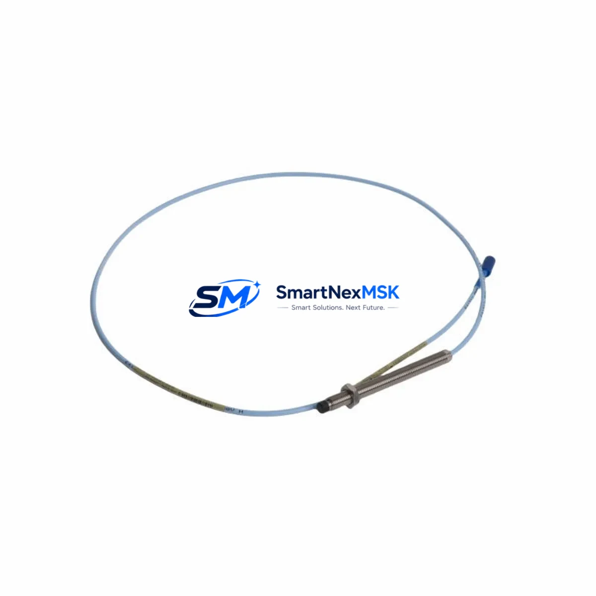
Bently Nevada 330104-00-24-05-01-00 Retrofit-Ready Proximity Transducer for 3300 XL Control Systems
The Bently Nevada 330104-00-24-05-01-00 is a high-precision eddy-current proximity transducer engineered for the 3300 XL Series vibration monitoring platform. As legacy machinery continues to operate well beyond its original design life, this transducer serves as a critical retrofit component for plants undertaking control system modernization, predictive maintenance upgrades, and obsolete-part replacement programs. Whether you are replacing a failed unit on a running turbine train, upgrading an aging 3300 Series rack to the 3300 XL standard, or restoring a mothballed compressor line, the 330104-00-24-05-01-00 provides a verified drop-in solution with full backward compatibility to existing wiring, conduit runs, and monitor channel assignments.
This transducer operates on the standard Bently Nevada 5-metre extension cable and driver architecture. It is fully compatible with the 3300 XL 8mm Proximity Transducer System and integrates directly with the 3300/16 Monitor, 3500/42M Proximitor/Seismic Monitor, and 3500/40M Proximitor Monitor rack-mounted modules without requiring firmware changes or channel reconfiguration. For plants running the System 1 or System 1 Evolution condition monitoring software, no driver update is required when substituting this unit for the original installed transducer.
Upgrade Compatibility Table
| Parameter | Detail |
|---|---|
| SKU / Part Number | 330104-00-24-05-01-00 |
| Series Compatibility | Bently Nevada 3300 XL, 3300, 3500 Series |
| Transducer Type | Eddy-Current Proximity (8 mm) |
| Cable Length | 5 m integral cable (extension cable required for full system) |
| Thread / Mounting | M10 x 1 threaded body; compatible with existing conduit and bracket hardware |
| Connector Interface | Standard Bently Nevada coaxial connector; mates with 330130 / 330180 extension cables |
| Target Material | AISI 4140 steel (standard); verify gap voltage for non-standard alloys |
| Operating Temperature | -35 °C to +121 °C |
| Communication / Signal | Analogue DC voltage output; compatible with 3300 XL Proximitor driver |
| Replacement Recommendation | Direct drop-in for 330104-00-24-05-01-00; verify gap setting (1.0 mm nominal) |
| Commissioning Note | Re-zero gap voltage at installation; confirm OK/NOT OK relay thresholds in monitor |
| Warranty | 12 Months from date of shipment |
Retrofit Planning for Existing Automation Systems
Successful integration of the 330104-00-24-05-01-00 into an existing machinery protection system begins well before the transducer arrives on site. Engineers should first audit the installed 3300 XL Proximitor driver (typically mounted in the field junction box or directly on the machine pedestal) to confirm the driver’s bias voltage output is within specification — a degraded driver will cause the replacement transducer to report false NOT OK conditions regardless of mechanical gap. If the driver is also beyond its service life, a concurrent replacement with a 330180-51-05 extension cable and driver assembly is strongly recommended to avoid a second outage.
At the rack level, verify that the host 3500/40M or 3500/42M monitor module channel configuration matches the transducer’s scale factor (200 mV/mil or 7.87 V/mm). Mismatched scale factors are a common source of erroneous vibration readings after transducer replacement and must be corrected in the monitor’s configuration software before returning the machine to service. If the plant is running an older 3300/16 Monitor rather than the 3500 Series rack, confirm that the channel’s full-scale range and alert/danger setpoints are documented before any hardware swap — these settings are stored in the monitor hardware and may not be recoverable if the module is also replaced.
For plants migrating from the legacy 3300 Series to the 3300 XL platform, the physical rack and 3300 XL Rack Interface Module (RIM) must be inspected for backplane connector integrity. Corroded or mechanically stressed backplane pins are a frequent cause of intermittent channel faults that are incorrectly attributed to the transducer. A full rack inspection — including the 3300 XL Power Supply module and any installed 3300 XL Keyphasor module — should be completed as part of the retrofit scope to avoid latent failures after recommissioning.
Wiring adaptation is straightforward: the 330104-00-24-05-01-00 uses the same coaxial signal path as its predecessors, so existing conduit, cable trays, and junction box terminations can be reused without modification. However, engineers should inspect the 330130-080-00-00 extension cable for jacket damage, moisture ingress at connectors, and shield continuity before reuse. A damaged extension cable will introduce noise into the vibration signal and may cause nuisance trips during startup. Where cable replacement is required, the 330130-080-00-00 or 330180-51-05 assemblies are the standard retrofit choices for 5-metre and 8-metre runs respectively.
If the plant’s control narrative includes a Keyphasor signal for phase-referenced vibration analysis, confirm that the 3300 XL Keyphasor transducer and its associated driver are also within calibration. A degraded Keyphasor signal will corrupt 1X and 2X vector data in System 1, making post-retrofit vibration trending unreliable. This is particularly important for plants using the data for rotor balancing or bearing fault detection.
Downtime Control During System Migration
Minimizing production loss during a proximity transducer replacement requires a structured pre-outage preparation protocol. Before the maintenance window opens, the engineering team should capture a full snapshot of the existing monitor configuration using the 3500 Rack Configuration Software or equivalent — including all channel scale factors, alert/danger setpoints, time delays, and relay assignments. This configuration file should be stored offline and verified against the as-built documentation before any hardware is disturbed.
Where the plant’s safety instrumented system (SIS) or distributed control system (DCS) receives vibration signals from the 3500 rack via Modbus RTU, FOUNDATION Fieldbus, or hardwired 4–20 mA outputs, the control room team must be notified before the channel is taken out of service. Placing the affected monitor channel in bypass mode — rather than allowing it to trip — prevents spurious shutdowns during the transducer swap and gap-setting procedure. The bypass should be formally logged in the permit-to-work system and removed immediately after the new transducer is verified in service.
The physical replacement of the 330104-00-24-05-01-00 typically requires less than 30 minutes of hands-on time at the machine, provided the replacement unit, calibrated gap-setting tool, and a digital voltmeter are staged in advance. After installation, the gap voltage should be measured at the driver output and confirmed within the ±0.5 V tolerance of the nominal bias point before the channel bypass is removed. A brief coast-down or bump test, where operationally permissible, provides additional confidence that the new transducer is tracking shaft motion correctly before the machine is returned to full load.
For plants with multiple identical transducer positions — such as turbine-generator sets with X-Y proximity probe pairs on each bearing — a rolling replacement strategy (one bearing at a time, with the machine running) can eliminate the need for a planned outage entirely, provided the plant’s operating procedures permit single-channel bypass during normal operation.
Retrofit Support FAQ
Q1: Is the 330104-00-24-05-01-00 a direct replacement for the older 330104-00-24-05-00-00 variant?
Yes. The -01-00 suffix denotes a minor revision to the connector body material for improved corrosion resistance. The electrical characteristics, scale factor, thread dimensions, and cable interface are identical. No wiring changes or monitor reconfiguration are required when substituting the -01-00 for the -00-00 variant.
Q2: What gap voltage should I set after installing the replacement transducer?
For standard AISI 4140 steel targets, the nominal gap is 1.0 mm (39.4 mil), corresponding to a bias voltage of approximately -10.0 VDC at the driver output. Confirm the exact target voltage from the original system documentation or the 3300 XL Transducer Installation Manual. For non-standard target materials (stainless steel, titanium, Inconel), a material correction factor must be applied — contact your instrumentation engineer before setting the gap.
Q3: Will this transducer work with the 3500/42M monitor without reconfiguration?
Yes, provided the existing channel is already configured for an 8 mm proximity transducer with a 200 mV/mil (7.87 V/mm) scale factor. If the channel was previously configured for a different transducer type or scale factor, the 3500 Rack Configuration Software must be used to update the channel parameters before the replacement transducer is placed in service.
Q4: What does the 12-month warranty cover?
All units supplied by SMARTNEXMSK carry a 12-month warranty from the date of shipment, covering manufacturing defects and premature failure under normal operating conditions. Units showing evidence of mechanical damage, incorrect installation, or operation outside the specified environmental limits are excluded. Warranty claims are processed via our sales team with a return merchandise authorization (RMA) number issued within 2 business days.
© 2026 SMARTNEXMSK. All rights reserved.
Original Source: https://smartnexmsk.com
Contact: sales@smartnexmsk.com | +86 18259474341


