Bently Nevada 330104-00-24-10-02-CN Retrofit-Ready Proximity Transducer for 3300 XL Control Systems
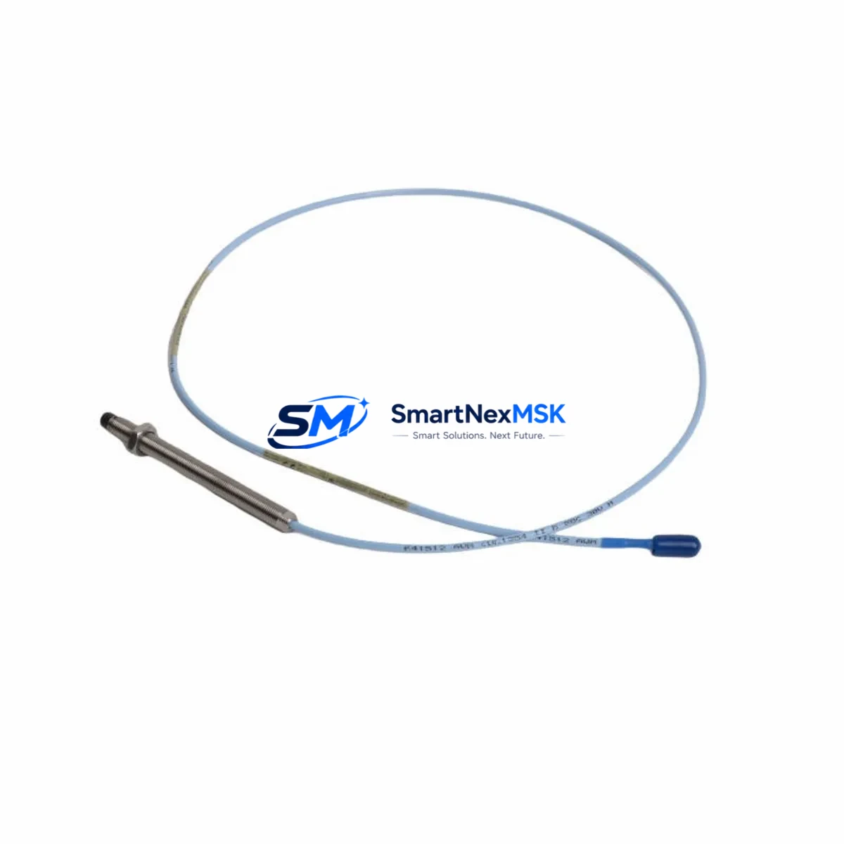
The Bently Nevada 330104-00-24-10-02-CN is an 8mm proximity transducer engineered for seamless compatibility with the 3300 XL Series vibration monitoring platform. As legacy rotating machinery protection systems approach end-of-life or face discontinued spare parts availability, this transducer serves as a verified drop-in replacement for aging 3300 Series and early 3300 XL installations. Whether you are managing a planned outage, responding to an unplanned failure, or executing a phased control system modernization, the 330104-00-24-10-02-CN delivers the signal integrity, dimensional compatibility, and wiring consistency required to restore or upgrade your machinery protection loop with minimal downtime.
This transducer is designed to interface directly with the Bently Nevada 3300 XL proximitor/extension cable system. It operates within the standard -24 VDC supply range and produces a linear output voltage proportional to the gap between the probe tip and the observed target shaft. The 330104-00-24-10-02-CN is compatible with the standard 3300 XL 8mm extension cable (330130 series) and the 3300 XL proximitor (330180 series), allowing field technicians to replace only the probe assembly without disturbing the existing cable routing or proximitor mounting. This is a critical advantage in confined turbine bearing housings or compressor pedestals where cable re-routing would extend shutdown duration significantly.
Upgrade Compatibility Table
| Parameter | 330104-00-24-10-02-CN | Notes / Retrofit Guidance |
|---|---|---|
| Probe Diameter | 8 mm | Direct fit for existing 8mm probe bosses; no machining required |
| Cable Length | 1.0 m integral cable | Pair with 330130 extension cable to reach proximitor; verify total system length |
| Supply Voltage | -24 VDC nominal | Compatible with 3300 XL proximitor power supply rail; no rewiring needed |
| Output Range | -2 VDC to -18 VDC | Matches 3300 XL monitor input range; no scale factor adjustment required |
| Thread / Mounting | M10 x 1 mm | Standard 3300 XL probe boss thread; confirm locknut torque per OEM spec |
| Communication / Protocol | Analog voltage (passive) | No protocol migration required; signal passes through proximitor to monitor |
| Monitor Compatibility | 3300 XL 11 mm / 8 mm monitors | Confirm monitor channel configured for 8 mm system in System 1 or rack keyswitch |
| Replacement for | 330104-00-24-10-02-CN, legacy 3300 8mm probes | Verify gap voltage at installation; retrim OK range in monitor if needed |
| Warranty | 12 Months | Covers manufacturing defects; includes pre-shipment functional test report |
Retrofit Planning for Existing Automation Systems
A successful retrofit of the 330104-00-24-10-02-CN into an operating plant begins well before the maintenance window opens. The first step is a system audit of the existing 3300 XL rack configuration. Technicians should document the current proximitor model (typically a 330180-51-00 or 330180-90-05), the extension cable part number and routed length, and the monitor slot assignment within the 3300 XL rack. The rack itself — often a 3300 XL 16-channel or 8-channel chassis — must have the correct channel type configured for an 8mm transducer system, which can be verified through the front-panel keyswitch position or through Bently Nevada System 1 software connected via the rack’s Ethernet or serial communication port.
Wiring continuity is the next critical checkpoint. The 330104-00-24-10-02-CN uses a standard coaxial signal path: center conductor carries the output voltage, and the shield is the return. When connecting to the 330130 extension cable, technicians must inspect the Swagelok-style connector for corrosion or mechanical damage, particularly in outdoor or high-humidity installations. The proximitor housing should be inspected for moisture ingress before reconnection. If the existing 330180 proximitor shows drift or calibration failure, it is advisable to replace it simultaneously with the probe to avoid a second outage for proximitor swap.
For plants running Bently Nevada System 1 Evolution software, the channel configuration screen allows engineers to verify the transducer scale factor, gap voltage OK limits, and alert/danger setpoints before the machine is returned to service. If the installation is part of a broader migration from an older 3300 Series rack to a 3500 Series rack — a common upgrade path for turbines requiring API 670 fifth-edition compliance — the 330104-00-24-10-02-CN remains compatible with 3500/42M and 3500/40M proximity monitor modules, provided the system length (probe + extension cable) falls within the qualified range. In such migrations, the 3500 rack’s TDI (Transducer Driver Interface) module and the associated I/O terminal block must be confirmed for 8mm system compatibility before the probe is installed.
Plants executing I/O expansion or control cabinet upgrades alongside the transducer replacement should also account for the DCS or safety system interface. The 3300 XL monitor outputs — typically 4–20 mA process outputs and relay contacts for alert and danger — connect to the plant DCS through marshalling panels or directly to I/O cards. If the DCS I/O cards are being replaced as part of the same project, the new analog input cards must be ranged to accept the 4–20 mA signal from the 3300 XL monitor. HMI faceplate graphics tied to the vibration channel tag should be reviewed to confirm that engineering unit scaling and alarm limits remain consistent after the hardware swap.
Downtime Control During System Migration
Minimizing production loss during a proximity transducer replacement requires a structured pre-outage preparation protocol. Before the machine is shut down, the existing gap voltage should be recorded from the System 1 trend display or the monitor front-panel meter. This baseline value — typically between -9.5 VDC and -10.5 VDC for a properly gapped 8mm probe on a steel shaft — serves as the target during reinstallation of the 330104-00-24-10-02-CN.
During the outage, the replacement probe should be pre-gapped on the bench using a gap tool or feeler gauge to the OEM-specified gap distance (typically 1.0 mm to 1.5 mm for 8mm probes on steel targets), then installed and fine-adjusted in the bearing housing with the shaft stationary. The gap voltage should be confirmed with a calibrated digital voltmeter at the proximitor output terminals before the monitor channel is re-enabled. This eliminates the risk of a false danger trip on machine restart caused by an out-of-range gap condition.
Original program logic in the DCS or safety PLC does not require modification for a like-for-like probe replacement. The 4–20 mA output from the 3300 XL monitor and the relay contact assignments remain unchanged. If the replacement is part of a rack migration to a 3500 Series system, the PLC or DCS tag database should be updated to reflect any new I/O card addresses, and a loop check should be performed on each channel before the machine is released for startup. Keeping a pre-tested spare 330104-00-24-10-02-CN on the shelf — alongside a matched 330130 extension cable and a 330180 proximitor — is the most effective strategy for reducing mean time to repair on future unplanned outages.
Retrofit Support FAQ
Q: Is the 330104-00-24-10-02-CN a direct replacement for the older 330104-00-24-10-02 without the CN suffix?
A: Yes. The CN suffix denotes the connector style on the integral cable. The transducer body, thread, probe diameter, and electrical characteristics are identical. The replacement is mechanically and electrically interchangeable in all standard 3300 XL 8mm system installations.
Q: Do I need to recalibrate the 3300 XL monitor after replacing the probe?
A: Full recalibration of the monitor is not required for a like-for-like replacement. However, you must verify and adjust the physical gap to achieve the correct gap voltage (typically -10 VDC ±0.5 VDC on steel). Alert and danger setpoints in the monitor do not change unless the machine’s vibration acceptance criteria have been revised.
Q: Can this transducer be used with a 3500 Series rack during a phased migration?
A: Yes, provided the total system length (probe integral cable + extension cable) is within the qualified range for the 3500/42M or 3500/40M proximity monitor module. Confirm system length compatibility in the 3500 Series TDI documentation before installation.
Q: What does the 12-month warranty cover, and is a test report included?
A: The 12-month warranty covers manufacturing defects in materials and workmanship from the date of shipment. Each unit undergoes a pre-shipment functional test verifying output linearity and gap voltage response. A test report is available upon request and can be provided with the shipment for incoming inspection records.
© 2026 SMARTNEXMSK. All rights reserved.
Original Source: https://smartnexmsk.com
Contact: sales@smartnexmsk.com | +86 18259474341


