Bently Nevada 330104-00-24-50-02-00 Spare 3300 XL Automation
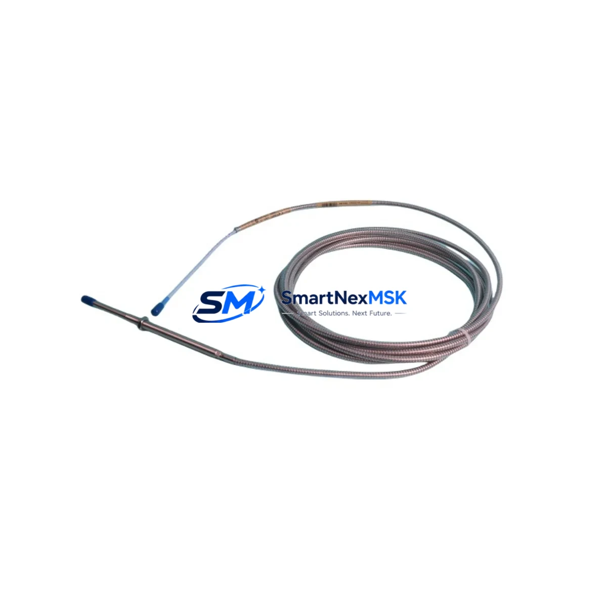
The Bently Nevada 330104-00-24-50-02-00 is an original eddy-current proximity transducer engineered for the 3300 XL Monitoring System — one of the most widely deployed vibration and position monitoring platforms in rotating machinery protection. For maintenance engineers managing turbines, compressors, pumps, and gearboxes, this transducer is a critical front-line sensing element. When it fails or degrades, the entire protection loop is compromised. Stocking a verified replacement is not optional — it is a fundamental requirement of any serious predictive maintenance or emergency spare parts program.
This unit features a 5 mm probe tip diameter, a 24-inch (610 mm) armored extension cable, and is calibrated for the standard Bently Nevada output range of –24 VDC with a sensitivity of 200 mV/mil (7.87 V/mm). It is designed for direct replacement in any 3300 XL channel without recalibration of the monitor, provided the full transducer system — probe, extension cable, and proximitor — is replaced as a matched set.
Spare Maintenance Table
| Parameter | Specification |
|---|---|
| SKU / Part Number | 330104-00-24-50-02-00 |
| Brand | Bently Nevada |
| Series | 3300 XL Monitoring System |
| Sensor Type | Eddy-Current Proximity Transducer |
| Probe Tip Diameter | 5 mm |
| Cable Length | 24 inches (610 mm) |
| Output Sensitivity | 200 mV/mil (7.87 V/mm) |
| Supply Voltage | –24 VDC nominal |
| Linear Range | 10–90 mil (0.25–2.29 mm) |
| Operating Temperature | –35°C to +177°C (probe); –35°C to +85°C (cable) |
| Target Material Compatibility | AISI 4140 steel (standard); other alloys require gap calibration |
| Connector Type | 3-pin MIL-C-5015 style |
| Installation Thread | M8 × 1.0 mm |
| Ingress Protection | IP67 (probe body) |
| Compatible Monitor | Bently Nevada 3300 XL Series (3300/16, 3300/20, 3300/25, 3300/46, 3300/55) |
| Compatible Proximitor | 330180 Series Proximitor Sensor |
| Application | Radial vibration, axial position, differential expansion, eccentricity |
| Warranty | 12 Months from date of shipment |
| Condition | Original, tested before shipment |
Maintenance Planning for Continuous Operation
When a 330104-00-24-50-02-00 proximity transducer is flagged for replacement during a planned outage or emergency shutdown, experienced maintenance engineers know that the transducer itself is rarely the only component requiring attention. A thorough inspection of the full measurement chain is essential to restore system integrity and prevent repeat failures.
Begin with the 330180 Series Proximitor Sensor — the signal conditioning module that pairs with this probe. If the transducer has been in service for more than three years or has been exposed to high-temperature excursions, the proximitor should be bench-tested or replaced simultaneously. A degraded proximitor will produce erratic gap voltage readings even with a new probe installed.
Next, inspect the 330130 extension cable connecting the probe to the proximitor. Cable jacket cracking, connector corrosion, and shield continuity failures are common in high-vibration environments and are frequently misdiagnosed as probe failures. Verify shield-to-ground continuity and insulation resistance before reinstalling.
At the monitor rack level, check the 3300/16 or 3300/20 monitor module input card for any alarm relay latching, blown input protection fuses, or relay contact wear on the 3300/46 relay module. These relay outputs drive shutdown logic and must be verified functional after any transducer replacement.
For systems using a 3300/55 keyphasor module, confirm that the reference signal is clean and phase-locked before returning the machine to service — a corrupted keyphasor signal will invalidate all synchronous vibration measurements across the entire rack.
Power supply integrity is equally critical. The 3300 Power Supply module (typically –24 VDC regulated) should be load-tested and output ripple measured. A power supply operating near end-of-life can introduce noise that mimics vibration events, triggering nuisance trips. If the cabinet houses a Bently Nevada 3500 series rack alongside legacy 3300 XL modules, verify that the common DC bus is properly isolated and that no ground loops exist between the two systems.
For facilities running System 1 Evolution or System 1 Condition Monitoring Software, update the channel configuration to reflect the new transducer serial number and re-baseline the gap voltage after installation. This ensures that trend data remains continuous and that alarm setpoints are correctly referenced to the new probe’s calibration curve.
Finally, document the replacement in your CMMS and update the spare parts register. A single 330104-00-24-50-02-00 transducer should be held as a minimum on-site spare for every two to four installed channels, with a recommended replenishment trigger at 50% stock depletion to account for lead times on original Bently Nevada components.
Site Replacement Workflow
Step 1 — Pre-Replacement Verification: Confirm the installed probe part number against the channel configuration in the 3300 XL monitor. Verify that the replacement 330104-00-24-50-02-00 matches the cable length, tip diameter, and connector type of the outgoing unit. Do not substitute a different cable length without recalculating the gap voltage setpoints.
Step 2 — Safe Isolation: Place the affected monitor channel in bypass mode via the front-panel keyswitch or System 1 software to prevent a spurious shutdown during probe removal. Confirm bypass status on the relay module before proceeding.
Step 3 — Probe Removal and Gap Inspection: Remove the probe using the correct spanner to avoid thread damage. Inspect the probe bore for contamination, oil ingress, or mechanical damage. Clean the bore and verify the target surface is free of scoring or runout anomalies that could affect the new probe’s linear range.
Step 4 — Installation and Gap Setting: Install the new 330104-00-24-50-02-00 and set the initial gap to the midpoint of the linear range (approximately 50 mil / 1.27 mm). Connect the extension cable and proximitor, then measure the DC gap voltage at the proximitor output. Adjust the probe gap until the output reads within the specified range for the target material.
Step 5 — System Restoration and Verification: Remove the channel bypass, observe the vibration reading for a minimum of 15 minutes at operating speed, and confirm that the reading is stable and within historical baseline. Update System 1 with the new gap voltage baseline and close the work order with full documentation of the as-left gap voltage, probe serial number, and installation date.
This workflow minimizes downtime, eliminates repeat failures caused by incomplete replacement, and ensures full compatibility with the 3300 XL protection system without requiring monitor reconfiguration.
Spare Parts Support FAQ
Q1: Is the 330104-00-24-50-02-00 compatible with both 3300 XL and 3500 series monitors?
The 330104-00-24-50-02-00 is specifically calibrated for the 3300 XL system. While the physical connector and output range are similar to some 3500 series transducers, cross-system use requires verification of the monitor’s input configuration and gap voltage setpoints. We recommend confirming compatibility with your system documentation before installation.
Q2: What testing is performed before shipment?
Every unit undergoes electrical continuity testing, insulation resistance measurement, and gap voltage output verification against a calibrated steel target before shipment. A test report is available upon request. Units are shipped in anti-static packaging with protective probe tip covers to prevent damage in transit.
Q3: How should I manage spare stock for a plant with 20+ installed channels?
Industry best practice for critical rotating machinery protection is to maintain a minimum of 10% spare coverage — approximately one transducer per 8–10 installed channels — with a replenishment trigger at 50% depletion. For facilities with long procurement lead times or remote locations, a higher buffer of 15–20% is recommended. Pairing the transducer spares with matched extension cables and proximitors as complete sets reduces replacement time and eliminates compatibility errors under pressure.
Q4: What is covered under the 12-month warranty?
The 12-month warranty covers manufacturing defects, electrical failure under normal operating conditions, and connector integrity. It does not cover damage resulting from incorrect installation, mechanical impact, chemical exposure, or operation outside the specified temperature and voltage range. Warranty claims are processed with return of the defective unit and a completed failure report. Replacement units are shipped within 3–5 business days of claim approval.
© 2026 SMARTNEXMSK. All rights reserved.
Original Source: https://smartnexmsk.com
Contact: sales@smartnexmsk.com | +86 18259474341


