Bently Nevada 330104-01-09-10-12-05: Retrofit-Ready 8mm Proximity Probe for 3300 XL Control Systems
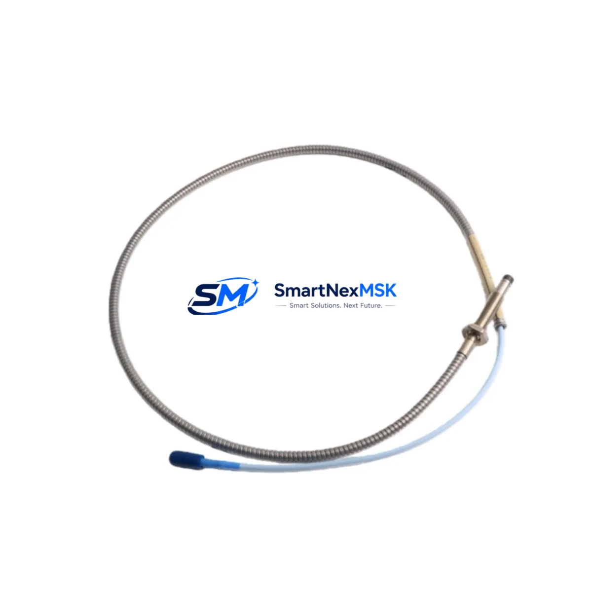
The Bently Nevada 330104-01-09-10-12-05 is an 8mm eddy-current proximity probe engineered for the 3300 XL Series vibration monitoring platform. Designed as a direct retrofit replacement for legacy 3300 Series probes, this unit delivers full electrical and mechanical compatibility with existing Proximitor® sensor housings, field wiring, and Bently Nevada System 1 software configurations. Whether you are upgrading a turbine protection panel, replacing a failed probe on a compressor train, or modernising a legacy vibration monitoring loop, the 330104-01-09-10-12-05 provides a verified drop-in solution that minimises engineering rework and unplanned downtime.
Upgrade Compatibility Table
| Parameter | Detail |
|---|---|
| SKU / Part Number | 330104-01-09-10-12-05 |
| Series Compatibility | Bently Nevada 3300 XL, 3300 Series (legacy) |
| Probe Diameter | 8 mm |
| Cable Length | 9 m (extension cable) / 1.0 m (probe cable) |
| Thread | M10 × 1 |
| Connector Type | 3-pin MIL-C-5015 compatible |
| Proximitor Compatibility | 3300 XL 8mm Proximitor® (330180 series) |
| Communication / Output | –24 VDC bias, 200 mV/mil (7.87 V/mm) sensitivity |
| Replacement for | 330104-00-xx, 330100-xx-xx legacy variants |
| Installation Requirement | Standard M10 boss; no housing modification required |
| Commissioning Note | Verify gap voltage (–10 to –18 VDC) after installation |
| Warranty | 12 Months — covers manufacturing defects and functional failure |
Retrofit Planning for Existing Automation Systems
Successful integration of the 330104-01-09-10-12-05 into an operating plant begins well before the probe reaches the machine. Engineers should first audit the existing Proximitor® sensor — typically a 330180-51-00 or 330180-91-00 — to confirm that the driver electronics remain within calibration. The extension cable assembly (330130-080-00-00 or equivalent) must be inspected for jacket integrity and connector corrosion, as degraded cable insulation is a common source of false high-vibration trips that are incorrectly attributed to probe failure.
On the terminal cabinet side, verify that the 3300 XL rack accepts the probe channel assignment without address conflicts. In multi-channel racks housing both radial vibration and axial position modules — such as the 3300/16 or 3300/20 — confirm that the I/O slot mapping in System 1 software matches the physical wiring schedule. If the plant is migrating from an older 3500 Series rack to a 3300 XL platform, note that the 3500/42M and 3500/44M proximity I/O modules use a different terminal block pitch; adapter plates or re-termination at the JB will be required.
Power supply integrity is equally critical. The 3300 XL Proximitor® draws from a –24 VDC rail; confirm that the existing power supply module — often a 3300/05 or equivalent barrier-isolated supply — can sustain the additional load if multiple probes are being replaced simultaneously. Keyphasor® probes (typically 330104-00-06-10-02-05 or similar) share the same –24 VDC bus and must be accounted for in the load budget.
For plants running Modbus RTU or FOUNDATION Fieldbus communication between the vibration monitoring rack and the DCS, verify that the protocol gateway configuration does not require re-mapping after probe replacement. In most cases, the 330104-01-09-10-12-05 is a transparent electrical replacement and no gateway reconfiguration is needed. However, if the HMI faceplate displays engineering-unit scaling based on a probe sensitivity constant, update the System 1 configuration database to reflect the 200 mV/mil sensitivity of the new probe before returning the loop to service.
Where the retrofit involves replacing probes on a machine that also uses a 3300 XL Dual Voting Logic (DVL) module, ensure that the voting threshold settings are reviewed after commissioning. A probe with a slightly different gap voltage characteristic can shift the DVL trip point if the threshold was set tightly against the original probe’s output curve.
Downtime Control During System Migration
Minimising production loss during a proximity probe replacement requires a structured pre-outage preparation protocol. Before the planned maintenance window, pre-configure the replacement 330104-01-09-10-12-05 on a bench fixture: set the mechanical gap to achieve a bias voltage of –12 VDC ±0.5 VDC using a calibrated Proximitor® and a non-conductive gap-setting tool. Document the as-found gap voltage of the failed probe before removal — this value is essential for root-cause analysis and for setting the replacement to the same operating point.
During the outage, follow a parallel-path approach: while one technician removes the old probe and cleans the boss threads, a second technician should verify continuity and insulation resistance on the extension cable. If the cable passes, it can be reused, saving significant re-routing time. If the cable fails the IR test (typically <1 MΩ at 500 VDC), replace it with a pre-cut 330130-series extension matched to the original length to avoid signal attenuation.
After mechanical installation, perform a static gap check before energising the Proximitor®. Once energised, confirm the bias voltage at the Proximitor® output terminals and at the rack input terminals to rule out cable losses. Log the as-left gap voltage in the plant maintenance management system (CMMS) and update the System 1 trend baseline to prevent nuisance alarms during the first hours of operation. With this approach, total probe replacement time — including documentation — can typically be completed within a two-hour maintenance window, preserving the original control logic and HMI display configuration without modification.
Retrofit Support FAQ
Q1: Is the 330104-01-09-10-12-05 a direct replacement for the 330104-00-09-10-12-05?
Yes. The -01- revision designation indicates an updated connector and cable jacket material. The electrical output sensitivity (200 mV/mil), thread specification (M10 × 1), and Proximitor® compatibility are identical. No wiring changes are required at the terminal cabinet.
Q2: What gap voltage should I set after installation?
The recommended operating gap for the 330104-01-09-10-12-05 paired with a 3300 XL 8mm Proximitor® is –12 VDC ±0.5 VDC, corresponding to a physical gap of approximately 1.0–1.5 mm depending on target material. Always verify against the OEM installation drawing for your specific machine train.
Q3: Has the unit been tested before shipment?
Yes. Each 330104-01-09-10-12-05 unit undergoes functional output verification and insulation resistance testing prior to dispatch. A test report is available upon request. The unit is covered by a 12-month warranty against manufacturing defects and functional failure from the date of shipment.
Q4: Can this probe be used with a 3500 Series rack?
The 330104-01-09-10-12-05 is optimised for the 3300 XL platform. While the electrical output is compatible with 3500/42M proximity I/O modules in principle, Bently Nevada’s system qualification is specific to the 3300 XL Proximitor®. For 3500 Series applications, consult the 3500/42M installation manual and verify channel configuration before installation.
© 2026 SMARTNEXMSK. All rights reserved.
Original Source: https://smartnexmsk.com
Contact: sales@smartnexmsk.com | +86 18259474341


