Bently Nevada 330104-01-17-05-01-05 Retrofit-Ready Proximity Transducer for 3300 XL Control Systems
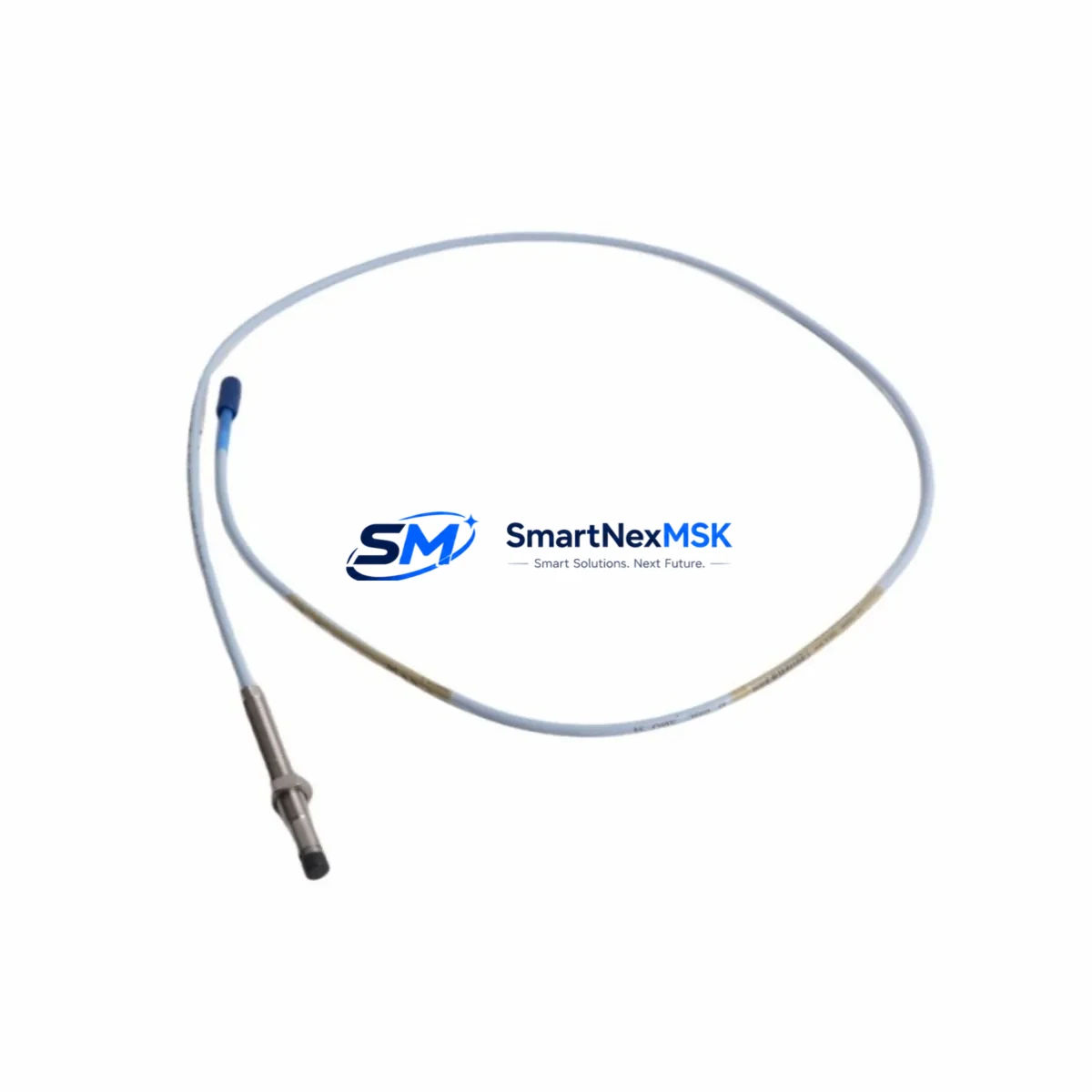
The Bently Nevada 330104-01-17-05-01-05 is an 8mm proximity transducer designed for the 3300 XL Series vibration monitoring platform. As legacy installations age and OEM support for discontinued configurations becomes increasingly limited, this unit serves as a verified retrofit-ready replacement for facilities operating Bently Nevada 3300 XL systems in turbomachinery protection, rotating equipment monitoring, and critical asset management applications. SMARTNEXMSK maintains in-stock inventory of this SKU to support unplanned outages, scheduled turnarounds, and phased system modernization programs.
Upgrade Compatibility Table
| Parameter | Detail |
|---|---|
| SKU / Part Number | 330104-01-17-05-01-05 |
| Series | Bently Nevada 3300 XL |
| Transducer Type | 8mm Proximity Transducer |
| Probe Length | 17 inches (432 mm) |
| Cable Length | 5 meters (integral) |
| Connector Type | 3-pin MIL-spec, compatible with 3300 XL extension cables |
| Mounting Thread | M10 x 1.0 |
| Gap Voltage Range | -10 VDC to -18 VDC (nominal -12 VDC at 1.0 mm gap) |
| Compatible Extension Cables | 330130 series (5m, 9m, 15m) |
| Compatible Driver / Proximitor | 3300 XL 8mm Proximitor Sensor (330180 series) |
| Compatible Monitor Cards | 3300/16, 3300/20, 3500/42M, 3500/45 |
| Replacement For | 330104-01-17-05-01-05 (same SKU, discontinued batch); also cross-compatible with 330103 series in many installations |
| Installation Requirement | Verify gap voltage at commissioning; re-zero monitor channel after swap |
| Communication Compatibility | Analog 4–20 mA output via Proximitor; compatible with 3500 rack Modbus/TCP and System 1 software |
| Retrofit Recommendation | Direct drop-in; no firmware change required on 3300 XL or 3500 racks |
| Commissioning Focus | Gap voltage verification, sensitivity calibration (200 mV/mil), and alarm setpoint confirmation |
| Warranty | 12 Months from date of shipment |
Retrofit Planning for Existing Automation Systems
Replacing a proximity transducer in a live turbomachinery protection system requires careful coordination across multiple subsystems. The 330104-01-17-05-01-05 probe interfaces directly with the 330180 series Proximitor Sensor, which conditions the raw eddy-current signal before it reaches the monitor rack. When planning a retrofit, engineers should first confirm that the existing 330130 series extension cable is undamaged and within specification — a degraded cable will introduce signal noise even with a new probe installed. The Proximitor output feeds into monitor cards such as the 3500/42M Machinery Protection Monitor or the 3300/16 Dual Vibration Monitor, and the channel must be bypassed or placed in trip-inhibit mode during the physical swap to prevent spurious shutdowns.
For facilities running the Bently Nevada System 1 condition monitoring software, the channel configuration — including full-scale range, alert setpoints, and danger setpoints — is stored at the rack level in the 3500 rack configuration file. After installing the replacement 330104-01-17-05-01-05, technicians should use the 3500 Rack Configuration Software to verify that the channel sensitivity is set to 200 mV/mil and that the gap voltage reads within the -10 to -18 VDC window at the target installation gap (typically 1.0 mm for steel targets). If the installation uses a 3300 XL Proximitor rather than a 3500 rack, the same gap and sensitivity checks apply, but configuration is managed locally at the Proximitor terminal block rather than through software.
In control cabinet upgrades where the 3300 XL rack is being migrated to a 3500 Series rack, the 330104-01-17-05-01-05 probe remains fully compatible — no probe-side changes are required. The migration effort centers on re-terminating the 330130 extension cable at the new rack’s I/O terminal block, updating the rack configuration file, and re-establishing the Modbus/TCP or RS-232 communication link to the plant DCS or historian. Facilities using a Rockwell Automation ControlLogix or Allen-Bradley PLC as the supervisory controller will need to update the EDS file or AOI (Add-On Instruction) to reflect the new rack address if the 3500 rack’s node ID changes during the migration. Similarly, any HMI screens built in FactoryTalk View or Wonderware InTouch that display vibration trend data from this channel should be reviewed to confirm tag mapping remains intact after the rack reconfiguration.
For I/O expansion projects where additional measurement points are being added to an existing 3500 rack, the 330104-01-17-05-01-05 can be deployed on new channels alongside existing probes without disrupting the installed base. The 3500 rack supports hot-insertion of monitor cards in most configurations, allowing new channels to be commissioned without a full system shutdown — a significant advantage in continuous-process industries where planned outages are infrequent.
Downtime Control During System Migration
Minimizing unplanned downtime during a proximity transducer replacement begins with pre-staging. Before the maintenance window opens, verify that the replacement 330104-01-17-05-01-05 has been bench-tested against a known-good Proximitor and that the gap voltage and sensitivity readings are within specification. Document the existing channel configuration — including alert and danger setpoints, time delays, and voting logic — from the 3500 Rack Configuration Software or the 3300 XL local configuration, so that settings can be restored exactly if the rack configuration is inadvertently altered during the swap.
During the swap, place the affected monitor channel in bypass or trip-inhibit mode using the rack’s front-panel keyswitch or through System 1 software. This preserves the protection logic on all other channels while the target channel is offline. If the installation uses a 2-out-of-3 (2oo3) voting architecture across multiple 3500/42M cards, the remaining two channels continue to provide protection coverage during the single-channel outage, further reducing risk. After the new probe is installed and the gap is set, restore the channel from bypass, confirm the gap voltage and vibration baseline, and verify that the System 1 trend display is updating correctly before closing the work order. The entire process — from bypass to restoration — can typically be completed in under two hours for a single-channel swap, keeping total production impact minimal.
For facilities without a redundant voting architecture, coordinating the swap during a planned low-load period or a scheduled inspection window is strongly recommended. SMARTNEXMSK can support expedited shipping to compress the logistics lead time, and our technical team can provide pre-shipment test reports to confirm that the unit is ready for immediate installation upon arrival.
Retrofit Support FAQ
Q1: Is the 330104-01-17-05-01-05 a direct drop-in replacement for my existing probe?
Yes. The 330104-01-17-05-01-05 is a direct replacement for units of the same part number and is cross-compatible with 330103 series probes in most 3300 XL installations. Verify the mounting thread (M10 x 1.0), probe length (17 inches), and cable length (5 meters) match your installation before ordering. No firmware or configuration changes are required on the monitor rack.
Q2: What commissioning steps are required after installation?
After physical installation, set the probe gap to the target distance (typically 1.0 mm for steel targets) and verify that the Proximitor output reads between -10 VDC and -18 VDC. Confirm channel sensitivity is configured to 200 mV/mil in the rack configuration software. Restore the channel from bypass mode, observe the vibration baseline for a short stabilization period, and confirm that alert and danger setpoints are active before returning the machine to service.
Q3: Can this probe be used with a 3500 Series rack as part of a system upgrade?
Yes. The 330104-01-17-05-01-05 is fully compatible with 3500 Series racks when paired with the appropriate 330180 series Proximitor Sensor. The probe itself requires no modification; the migration effort is limited to re-terminating the extension cable at the new rack’s terminal block and updating the rack configuration file to reflect the channel’s sensitivity and setpoint parameters.
Q4: What warranty coverage is provided, and is pre-shipment testing available?
All units supplied by SMARTNEXMSK carry a 12-month warranty from the date of shipment, covering manufacturing defects and functional failures under normal operating conditions. Pre-shipment functional testing is available upon request, and test reports can be provided to support your incoming inspection process. Units are shipped with appropriate ESD protection and packaging to maintain integrity during transit.
© 2026 SMARTNEXMSK. All rights reserved.
Original Source: https://smartnexmsk.com
Contact: sales@smartnexmsk.com | +86 18259474341


