Bently Nevada 330104-03-09-10-02-00 3300 XL Spare: Precision Proximity Probe for Industrial Downtime Control
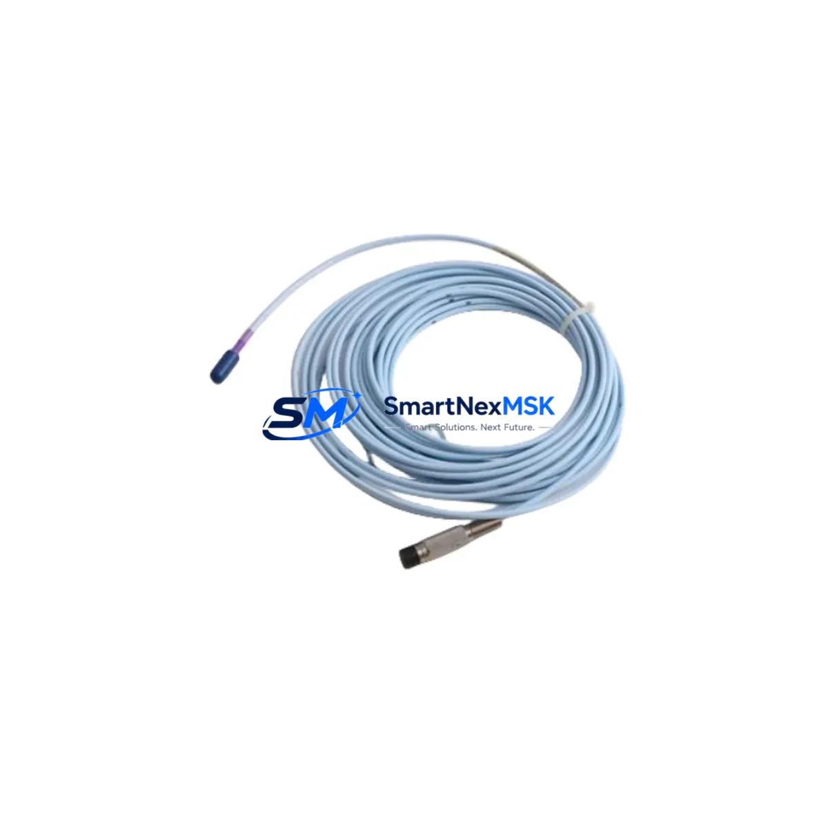
The Bently Nevada 330104-03-09-10-02-00 is an original 8mm eddy-current proximity probe engineered for the 3300 XL Proximity Transducer System. Designed for continuous shaft vibration and position monitoring in rotating machinery, this probe is a critical spare component in turbines, compressors, pumps, and generators across oil & gas, power generation, and heavy manufacturing facilities. When this probe fails or degrades, the entire vibration monitoring loop is compromised — triggering false alarms, masking real faults, or causing unplanned shutdowns. Maintaining a verified, tested replacement on the shelf is the single most effective way to restore monitoring integrity within hours, not days.
At SMARTNEXMSK, every 330104-03-09-10-02-00 unit is sourced from authorized supply chains, inspected against OEM specifications, and shipped with full traceability documentation. We support maintenance engineers and procurement teams who cannot afford ambiguity in spare parts sourcing.
Spare Maintenance Table
| Parameter | Specification |
|---|---|
| Part Number | 330104-03-09-10-02-00 |
| Brand | Bently Nevada |
| Series | 3300 XL Proximity Transducer System |
| Probe Type | 8mm Eddy-Current Proximity Probe |
| Cable Length | 3m (extension cable sold separately, e.g. 330130 series) |
| Thread Size | M10 × 1.0 |
| Sensitivity | 7.87 V/mm (200 mV/mil) |
| Linear Range | 0.25 – 2.54 mm (10 – 100 mil) |
| Operating Temperature | -35°C to +177°C |
| Supply Voltage | -24 VDC (via Proximitor® driver) |
| Compatible Driver | 3300 XL NSv Proximitor® (e.g. 330180 series) |
| Application | Shaft radial vibration, axial position, differential expansion |
| Installation Environment | Industrial — oil mist, high temperature, high vibration |
| Connector Type | Integral coaxial, armored cable |
| Compliance | API 670 compatible |
| Warranty | 12 Months from shipment date |
| Condition | Original / New surplus — tested before dispatch |
Maintenance Planning for Continuous Operation
When a 330104-03-09-10-02-00 proximity probe is flagged during routine vibration signature review or fails a gap voltage check, the replacement workflow must extend beyond the probe itself. A complete maintenance assessment of the transducer loop is essential to avoid repeat failures and ensure the monitoring system returns to full API 670 compliance.
Begin by verifying the Proximitor® driver module — typically a 330180-X1-05 or equivalent 3300 XL NSv driver — for correct output voltage and gap calibration. A degraded driver will cause the new probe to read incorrectly even if the probe itself is healthy. Next, inspect the 330130 series extension cable connecting the probe to the driver; cable damage, connector corrosion, or impedance mismatch are common root causes of intermittent vibration alarms that are misattributed to the probe.
At the junction box and marshalling cabinet level, check the terminal blocks and field wiring for continuity and insulation resistance. Moisture ingress in terminal enclosures near rotating equipment is a frequent cause of signal drift. If the machine train includes axial position monitoring, the paired 330104 axial probe and its dedicated driver channel should be re-gapped simultaneously to maintain differential expansion accuracy.
For facilities running System 1 or System 1 Evolution condition monitoring software, confirm that the channel configuration — probe type, sensitivity constant, and gap voltage setpoints — is updated to match the replacement probe’s calibration certificate. Mismatched sensitivity constants will produce incorrect vibration amplitude readings and may mask real machinery faults.
In control cabinets housing 3500 series rack-based monitoring systems, a proximity probe replacement is also an appropriate time to inspect the 3500/42M Proximitor®/Seismic Monitor I/O module, verify the 3500/20 rack power supply output rails, and check the 3500/92 communication gateway for firmware currency. Aging power supplies with marginal output voltage are a silent contributor to probe system instability.
Where the machine is part of a turbine control system integrated with a Woodward MicroNet or Mark VIe platform, ensure that the vibration trip relay outputs from the monitoring rack are re-tested after probe replacement. Relay contact resistance and trip setpoint drift should be verified before returning the machine to service. Signal isolators between the Proximitor® output and the DCS analog input card should also be checked for zero and span accuracy.
Finally, update the site’s spare parts register. A single 330104-03-09-10-02-00 probe consumed from stock should trigger a replenishment order. Best practice for critical rotating machinery is to maintain a minimum of two probes per machine train in the on-site spare parts inventory, alongside matched extension cables and at least one spare Proximitor® driver.
Site Replacement Workflow
Step 1 — Isolation and Lockout: Follow site LOTO procedures. Confirm the machine is at rest and the monitoring system is in bypass mode to prevent spurious trips during probe removal.
Step 2 — Gap Measurement of Existing Probe: Before removal, record the existing gap voltage using a calibrated voltmeter at the Proximitor® output. Document the reading against the historical baseline. A gap voltage outside the –10 to –18 VDC window confirms probe or cable degradation.
Step 3 — Probe Removal: Unscrew the probe from the bracket using the correct spanner. Do not apply torque to the cable. Inspect the probe tip for physical damage, pitting, or contamination from shaft surface irregularities.
Step 4 — Installation of 330104-03-09-10-02-00: Thread the replacement probe into the bracket by hand first, then torque to the manufacturer’s specification (typically 1.5 – 2.0 N·m for M10 probes). Set the initial gap to the midpoint of the linear range — approximately 1.27 mm (50 mil) — and verify the Proximitor® output reads within the calibrated gap voltage window.
Step 5 — System Verification: With the monitoring system returned to active mode, confirm that the vibration channel reads within the expected baseline range for the machine at rest (typically <25 µm pk-pk for well-balanced rotating equipment). Check that no alarms or trips are active before releasing the machine for restart.
Step 6 — Documentation: Record the replacement in the site CMMS, update the calibration record, and file the probe’s test certificate. Notify the condition monitoring team to reset the vibration trend baseline in System 1 or equivalent software.
Spare Parts Support FAQ
Q1: Is the 330104-03-09-10-02-00 compatible with both 3300 XL and older 3300 series Proximitor® drivers?
The 330104-03-09-10-02-00 is designed and calibrated for the 3300 XL NSv Proximitor® system. While the physical connector and thread are mechanically compatible with some earlier 3300 series drivers, the sensitivity constant (7.87 V/mm) must be matched to the driver’s configuration. Using this probe with a non-XL driver without recalibration may produce inaccurate gap and vibration readings. Always verify driver compatibility before installation.
Q2: What pre-shipment testing does SMARTNEXMSK perform on this probe?
Every 330104-03-09-10-02-00 unit undergoes electrical continuity verification, coil impedance measurement, and gap voltage output testing against a reference Proximitor® driver before dispatch. Units that do not meet OEM specification tolerances are quarantined and not shipped. A test record is available upon request.
Q3: How should this probe be stored if it is held as a long-term spare?
Store in the original anti-static packaging in a dry, temperature-controlled environment (10°C – 40°C, <70% RH non-condensing). Avoid storage near strong magnetic fields or sources of mechanical vibration. Inspect the probe tip and connector annually. Probes stored correctly retain full functionality for 5+ years. SMARTNEXMSK recommends rotating long-term spares into service and replenishing stock to maintain freshness.
Q4: What is covered under the 12-month warranty?
The 12-month warranty covers manufacturing defects, coil failure, connector integrity, and calibration accuracy under normal operating conditions as specified by Bently Nevada. It does not cover damage resulting from incorrect installation, shaft contact, chemical contamination, or operation outside the rated temperature and voltage range. Warranty claims are processed within 5 business days of receipt of the returned unit.
© 2026 SMARTNEXMSK. All rights reserved.
Original Source: https://smartnexmsk.com
Contact: sales@smartnexmsk.com | +86 18259474341


