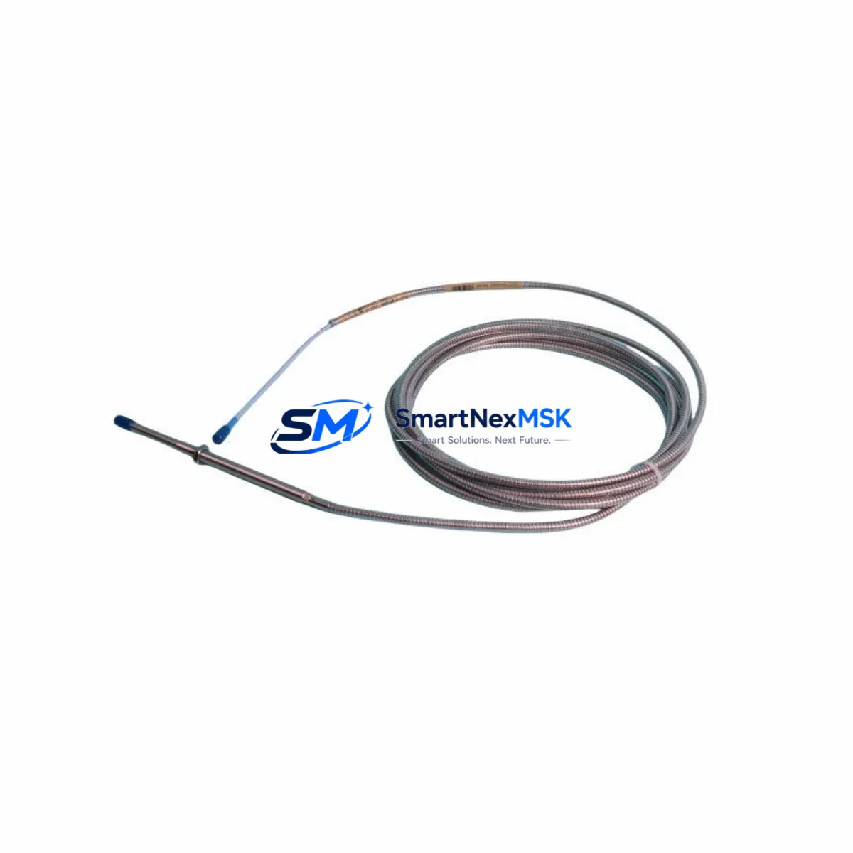
Bently Nevada 330104-03-10-05-02-00 Retrofit-Ready Proximity Transducer for 3300 XL Control Systems
The Bently Nevada 330104-03-10-05-02-00 is a high-precision eddy-current proximity transducer engineered for seamless integration into legacy and modernized 3300 XL vibration monitoring systems. As industrial facilities face increasing pressure to extend the operational life of aging machinery protection infrastructure, this transducer serves as a verified drop-in replacement for discontinued or end-of-life proximity probes within the Bently Nevada 3300 XL platform. Whether you are upgrading a turbine protection panel, retrofitting a compressor train monitoring rack, or restoring a critical machinery protection loop after an unplanned failure, the 330104-03-10-05-02-00 delivers the dimensional accuracy, signal linearity, and system compatibility required for a smooth, low-risk transition.
This transducer is designed for use with the standard 3300 XL extension cable and the 3300 XL proximitor sensor, forming a complete measurement chain that integrates directly with existing 3300 XL monitor cards such as the 3300/16 and 3300/20 series. The probe tip diameter, thread specification, and cable termination are fully compatible with existing probe holders and armored conduit installations, eliminating the need for mechanical rework during replacement. Engineers performing a like-for-like swap can retain the original probe bracket, lock nut, and target gap setting, significantly reducing installation time and the risk of introducing new mechanical variables into a calibrated measurement loop.
Before committing to a retrofit using the 330104-03-10-05-02-00, field engineers should verify several critical parameters. Power supply capacity at the proximitor housing must be confirmed, as the 3300 XL proximitor requires a regulated –24 VDC supply within the specified current budget of the barrier or junction box. Terminal wiring at the field junction box should be inspected for correct polarity and shield grounding, particularly in installations where the original cable has been spliced or re-terminated. Backplane slot assignments within the 3300 XL rack must be documented prior to removal of the existing probe, ensuring that the monitor channel address and rack configuration in the System 1 or Rack Configuration Software are preserved without requiring a full re-commission of the monitoring system.
Module address mapping is especially important in multi-channel racks where the 3300/16-channel monitor or 3300/20-channel monitor is configured for specific machine train positions. Any change to the physical channel assignment during a probe swap can cause alarm setpoint mismatches or trip relay mis-association in the control logic. Program compatibility should also be reviewed if the facility uses a DCS or safety system — such as a Triconex TMR controller or a Honeywell Safety Manager — that receives 4–20 mA or relay outputs from the 3300 XL monitor. Confirming that the analog output scaling and relay logic remain unchanged after the transducer replacement prevents nuisance trips during the post-installation verification run.
HMI screen updates are often overlooked during proximity transducer replacements. If the facility’s operator interface — whether a Wonderware InTouch station, a Rockwell FactoryTalk View display, or a custom SCADA screen — references the specific channel tag associated with the replaced probe, the engineering team should confirm that the tag name, engineering unit, and alarm threshold displayed on the HMI match the reconfigured monitor output. Communication link integrity between the 3300 XL rack and the plant DCS should be verified using the Modbus RTU or RS-232 serial link that is standard on many 3300 XL installations, ensuring that vibration data is correctly transmitted to the historian and alarm management system after the retrofit is complete.
Field commissioning of the 330104-03-10-05-02-00 follows the standard Bently Nevada gap voltage procedure. With the machine at rest, the probe is advanced toward the target shaft surface until the proximitor output reads within the linear range, typically –10 VDC at the nominal gap of 50 mils (1.27 mm) for standard 8 mm probes. The gap voltage is then recorded and compared against the original baseline to confirm that the new transducer’s sensitivity factor — expressed in mV/mil — matches the system calibration. Any deviation beyond the acceptable tolerance should be resolved before returning the machine to service, as an incorrect gap setting will shift the vibration amplitude reading and potentially mask or exaggerate actual shaft motion.
Upgrade Compatibility Table
| Parameter | 330104-03-10-05-02-00 Specification | Retrofit Notes |
|---|---|---|
| Compatible System | Bently Nevada 3300 XL | Direct replacement; no rack modification required |
| Probe Tip Diameter | 8 mm | Fits standard 3300 XL probe holders and brackets |
| Cable Length | 3 m (integral) | Pair with 3300 XL extension cable for longer runs |
| Proximitor Compatibility | 3300 XL Proximitor Sensor | Verify –24 VDC supply at proximitor housing |
| Monitor Compatibility | 3300/16, 3300/20 Series Monitors | Confirm channel address and slot assignment before swap |
| Communication Interface | Analog / Relay / Modbus RTU | Verify DCS tag mapping and serial link after installation |
| Installation Interface | Standard thread, armored conduit compatible | Retain original probe bracket and lock nut |
| Commissioning Method | Gap voltage procedure (–10 VDC @ 50 mil nominal) | Record and compare against original baseline |
| Warranty | 12 Months | Covers manufacturing defects; includes pre-shipment functional test |
Retrofit Planning for Existing Automation Systems
A successful retrofit of the 330104-03-10-05-02-00 into an existing machinery protection system requires a structured bill of materials review before the maintenance window opens. In a typical 3300 XL installation, the measurement chain includes the proximity probe, the 3300 XL extension cable (available in standard lengths of 5 m, 9 m, and 14 m), and the 3300 XL proximitor sensor mounted in the field junction box. The proximitor is powered from the rack’s power supply module — commonly the 3300/05 power supply — which feeds the backplane through the 3300 XL rack chassis. Engineers should confirm that the power supply module has sufficient current headroom to support the replacement transducer without triggering an undervoltage condition on the backplane.
In installations where the 3300 XL rack is integrated with a broader control architecture, the I/O wiring from the monitor’s relay outputs and 4–20 mA analog outputs typically terminates at a marshalling cabinet before connecting to the plant DCS or safety system. Reviewing the marshalling cabinet terminal block assignments and confirming continuity after the probe swap prevents signal interruption to downstream control loops. If the facility is also upgrading from an older 3300 series monitor to the current 3300 XL platform, the replacement of the monitor card itself — such as moving from a legacy 3300/10 to a 3300/16 — may require a corresponding update to the System 1 rack configuration file and a re-verification of all alarm and danger setpoints stored in the monitor’s non-volatile memory.
For facilities running Rockwell Automation ControlLogix or CompactLogix PLCs alongside the Bently Nevada monitoring system, the integration typically relies on a Modbus TCP/IP or DeviceNet gateway module that bridges the 3300 XL serial output to the PLC backplane. Confirming that the gateway’s register map remains consistent after the transducer replacement ensures that the PLC ladder logic — which may reference specific vibration amplitude or phase tags for interlock purposes — continues to function correctly without requiring a program download or processor restart. Similarly, if the plant uses a Siemens S7-300 or S7-400 controller in the same control cabinet, the PROFIBUS DP or PROFINET interface to the monitoring rack should be verified for correct node addressing after any hardware change.
Downtime Control During System Migration
Minimizing unplanned downtime during a proximity transducer replacement requires a pre-staged approach that keeps the original measurement loop active as long as possible. Where the machine protection system permits, the replacement probe should be pre-gapped and verified on the bench using a portable proximitor and a calibrated gap block before the maintenance window begins. This allows the field technician to confirm the transducer’s sensitivity factor and output linearity in advance, reducing the time the machine is unprotected during the actual swap.
During the replacement, the original program logic in the DCS or PLC should be placed in a maintenance override mode that suppresses trip outputs from the affected channel without disabling the monitoring function entirely. This approach preserves control continuity for the rest of the machine train while the probe is being changed. After the new 330104-03-10-05-02-00 is installed and gapped, the channel should be brought back online in monitor-only mode first, allowing the engineering team to confirm that the vibration reading is stable and within the expected baseline range before re-enabling the trip relay. The entire swap — from probe removal to trip re-enable — can typically be completed within a two-hour maintenance window when the pre-staging steps are followed, significantly reducing the risk of an extended unplanned outage.
All pre-shipment units are functionally tested before dispatch, and each 330104-03-10-05-02-00 is supplied with a 12-month warranty covering manufacturing defects. In-stock units are available for same-day or next-business-day dispatch, supporting emergency replacement scenarios where minimizing machine downtime is the primary constraint.
Retrofit Support FAQ
Q: Is the 330104-03-10-05-02-00 a direct replacement for the original Bently Nevada probe in my 3300 XL system?
A: Yes. The 330104-03-10-05-02-00 is dimensionally and electrically compatible with the standard 3300 XL measurement chain, including the 3300 XL proximitor sensor and 3300/16 or 3300/20 monitor cards. No mechanical rework or rack reconfiguration is required for a like-for-like swap.
Q: What wiring checks should I perform before installing the replacement transducer?
A: Verify the –24 VDC supply voltage at the proximitor housing, confirm correct polarity and shield grounding at the field junction box terminal block, and check that the extension cable is free of damage or splice points that could introduce signal noise. Document the original gap voltage before removal so you have a baseline for commissioning the new probe.
Q: How do I confirm compatibility with my DCS or safety system after the swap?
A: After installation and gapping, bring the channel online in monitor-only mode and verify that the 4–20 mA analog output and relay states at the marshalling cabinet match the expected values. Confirm that the Modbus RTU or serial communication link is transmitting correct vibration data to the DCS historian and that all HMI tags and alarm thresholds are displaying correctly before re-enabling the trip relay.
Q: What does the 12-month warranty cover, and is pre-shipment testing included?
A: The 12-month warranty covers manufacturing defects in materials and workmanship from the date of shipment. Every unit undergoes a functional pre-shipment test to verify output linearity and sensitivity factor before dispatch. Warranty claims are supported directly through SMARTNEXMSK with a target response time of one business day.
© 2026 SMARTNEXMSK. All rights reserved.
Original Source: https://smartnexmsk.com
Contact: sales@smartnexmsk.com | +86 18259474341


