Bently Nevada 330104-03-10-10-02-00 Retrofit-Ready Proximity Transducer for 3300 XL Control Systems
The Bently Nevada 330104-03-10-10-02-00 is an 8 mm proximity transducer designed for continuous vibration and position monitoring in rotating machinery applications. As part of the 3300 XL Series, this transducer delivers high-accuracy, non-contact measurement of shaft displacement, making it a critical component in turbine protection systems, compressor monitoring panels, and pump condition monitoring installations. With many legacy 3300 XL installations now approaching end-of-support cycles, the 330104-03-10-10-02-00 has become one of the most requested retrofit and replacement components in the industrial automation market.
Whether you are upgrading an aging vibration monitoring rack, replacing a failed transducer in a critical production line, or migrating from an earlier Bently Nevada 3300 platform to the current 3300 XL architecture, this unit provides a verified drop-in replacement path with no firmware changes required at the monitor level. The transducer is fully compatible with the 3300 XL proximitor/seismic monitor and integrates directly with existing field wiring, junction boxes, and DCS input cards without requiring re-termination of the armored extension cable.
Upgrade Compatibility Table
| Parameter | 330104-03-10-10-02-00 (Current) | Legacy 330104 Variants |
|---|---|---|
| Probe Diameter | 8 mm | 8 mm |
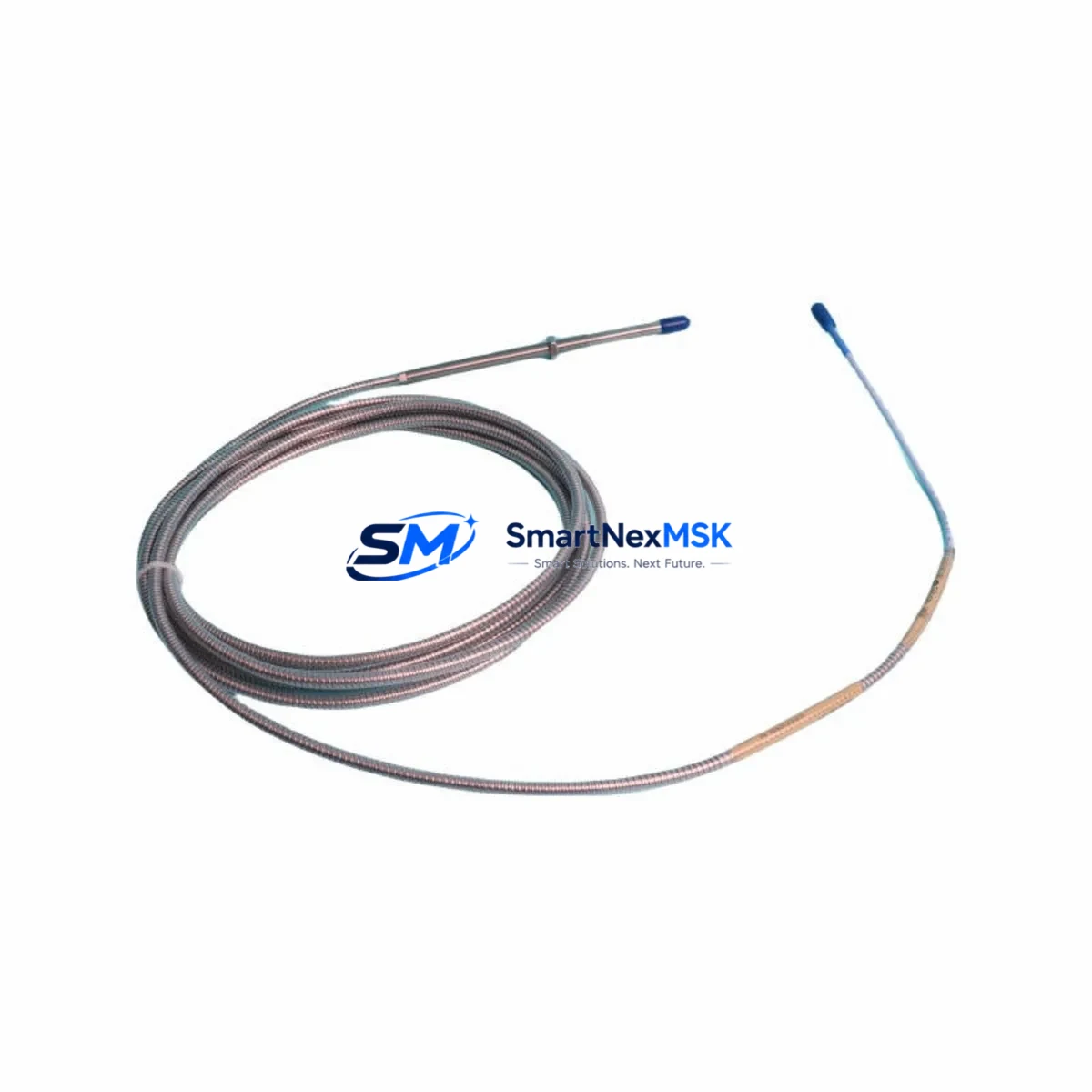
| Cable Length | 1.0 m (probe) + 5.0 m (extension) | Varies by suffix |
| Frequency Range | DC – 10,000 Hz | DC – 10,000 Hz |
| Output Sensitivity | 200 mV/mil (7.87 V/mm) | 200 mV/mil |
| Supply Voltage | -24 VDC (nominal) | -24 VDC |
| Target Material | AISI 4140 steel (recommended) | AISI 4140 steel |
| Connector Type | Standard BNC / MIL-C-5015 | Compatible |
| Monitor Compatibility | 3300 XL Proximitor Monitor | 3300 XL / 3300 Series |
| Installation | Direct mount, no bracket modification | Same |
| Communication | Analog 4–20 mA / voltage output to DCS | Analog |
| Replacement Recommendation | Direct drop-in for all -03-10-10-02-00 variants | Verify suffix before ordering |
| Commissioning Note | Re-gap required after installation (nominal 50 mil) | Same procedure |
| Warranty | 12 Months | N/A (OEM discontinued) |
Retrofit Planning for Existing Automation Systems
Retrofitting a proximity transducer in an operating plant requires careful coordination across multiple system layers. Before removing the existing 330104-03-10-10-02-00 or its predecessor, engineers should document the current gap voltage reading at the 3300 XL Proximitor Monitor to establish a baseline. This reading, typically between -10 VDC and -18 VDC depending on the installed gap, serves as the reference for post-installation verification.
In most 3300 XL installations, the transducer connects to the proximitor via a 3300 XL extension cable — commonly the 330130 series armored cable — which routes through the machine casing to the junction box. If the extension cable shows signs of insulation degradation or connector corrosion, it is advisable to replace it simultaneously with the probe to avoid a second outage. The 3300 XL Proximitor Monitor itself, such as the 3300/16 or 3300/20 dual-channel monitor card, should be inspected for alarm setpoint configuration and OK relay status before the transducer swap begins.
For installations where the 3300 XL rack also houses a 3300/55 Keyphasor module, the phase reference signal must remain stable throughout the transducer replacement to avoid triggering false vibration alarms on adjacent channels. If the control system feeds into a DCS platform via a 3500/22M transient data interface or a 3500/42M proximitor monitor card in a 3500 Series rack, the analog input scaling at the DCS I/O card should be verified against the new transducer’s sensitivity specification before returning the machine to service.
In modernization projects where the plant is migrating from the legacy 3300 platform to the 3500 Series rack-based system, the 330104-03-10-10-02-00 transducer remains compatible with 3500/42M monitor cards when used with the appropriate proximitor. This compatibility simplifies phased migration strategies, allowing the field transducer to remain in place while the monitoring rack is upgraded. The 3500 rack’s System 1 Evolution software can then be configured to accept the existing transducer signal without requiring a new field installation.
Power supply capacity is a common oversight in retrofit planning. The 3300 XL system draws -24 VDC from the rack power supply — typically the 3300/05 or equivalent — and adding replacement transducers to an already loaded rack should be preceded by a power budget review. Each 8 mm transducer system draws approximately 25–35 mA, and the total channel count must remain within the power supply’s rated output to prevent voltage droop that could affect OK threshold accuracy.
Downtime Control During System Migration
Minimizing unplanned downtime during a proximity transducer replacement is achievable with structured pre-outage preparation. The most effective approach is to pre-configure the replacement 330104-03-10-10-02-00 on a bench setup using a 3300 XL Proximitor and a calibrated target simulator before the maintenance window begins. This confirms the transducer’s output sensitivity and OK status before it enters the field, eliminating the risk of discovering a defective unit after the machine is already offline.
During the outage window, the original program logic in the DCS or safety system should not be modified. The 3300 XL monitor’s alarm inhibit function can be used to suppress nuisance alarms during the re-gapping procedure without altering the underlying setpoint configuration. Once the new transducer is installed and gapped to the nominal 50 mil (1.27 mm) specification, the gap voltage should be measured and recorded before re-enabling the alarm outputs.
If the plant operates a redundant monitoring architecture — for example, using a 3500/42M in a 1oo2 or 2oo3 voting configuration — the replacement can often be performed on one channel while the redundant channel remains in service, further reducing exposure to unprotected operation. After the replacement is complete, a full channel functional test including OK relay verification, alarm trip test, and DCS display confirmation should be completed before the machine is returned to normal operation. All test results should be documented in the plant’s maintenance management system to support future audit and reliability reviews.
Retrofit Support FAQ
Q1: Is the 330104-03-10-10-02-00 a direct replacement for earlier 330104 suffix variants?
In most cases, yes. The -03-10-10-02-00 suffix specifies an 8 mm probe with a 1.0 m probe cable, 5.0 m extension cable, and standard connector configuration. If your existing installation uses a different cable length suffix, verify the total system cable length against the 3300 XL proximitor’s linear range specification before ordering. Cable length directly affects the gap voltage range and OK threshold, so mismatched suffix combinations can cause nuisance OK faults even with a correctly installed probe.
Q2: What commissioning steps are required after installation?
After mechanical installation, the probe gap must be set to the nominal value specified in the machine’s original alignment documentation — typically 50 mil (1.27 mm) for standard 8 mm probes. Measure the gap voltage at the proximitor’s output connector and confirm it falls within the linear range. Re-enable alarm outputs, verify the OK relay closes, and confirm the DCS displays the correct vibration reading. A bump test or slow-roll check is recommended before returning the machine to full speed.
Q3: Can this transducer be used with the Bently Nevada 3500 Series monitoring system?
Yes, the 330104-03-10-10-02-00 is compatible with 3500 Series proximitor monitor cards, including the 3500/42M, when paired with the appropriate 3300 XL Proximitor. This makes it suitable for phased migration projects where the field transducer is retained while the monitoring rack is upgraded from the 3300 platform to the 3500 architecture.
Q4: What does the 12-month warranty cover, and how is it validated?
Each unit supplied by SMARTNEXMSK carries a 12-month warranty covering manufacturing defects and functional failure under normal operating conditions. Prior to shipment, every unit undergoes output sensitivity verification and OK threshold testing. A test report is available upon request. Warranty claims are supported by the serial number recorded at the time of shipment. Units showing evidence of mechanical damage, incorrect installation gap, or operation outside the specified supply voltage range are evaluated on a case-by-case basis.
—
© 2026 SMARTNEXMSK. All rights reserved.
Original Source: https://smartnexmsk.com
Contact: sales@smartnexmsk.com | +86 18259474341


