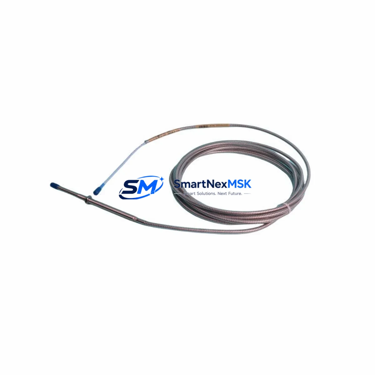
Bently Nevada 330104-04-15-05-02-00 3300 XL Spare: Precision Proximity Transducer for Industrial Downtime Control
The Bently Nevada 330104-04-15-05-02-00 is an original eddy-current proximity transducer engineered for the 3300 XL monitoring system — one of the most widely deployed vibration and position monitoring platforms in rotating machinery protection. For maintenance engineers managing turbines, compressors, pumps, and generators, this transducer is a critical front-line sensing element. When it fails or degrades, the entire vibration monitoring loop is compromised, creating unplanned downtime risk and potential machinery damage. Stocking a verified replacement is not optional — it is a core element of any responsible predictive maintenance program.
At SMARTNEXMSK, every 330104-04-15-05-02-00 unit is sourced from authorized supply channels, individually inspected, and function-tested prior to shipment. Each unit ships with a 12-month warranty and full traceability documentation, giving procurement engineers the confidence to approve the purchase and maintenance engineers the assurance to install without hesitation.
Spare Maintenance Table
| Parameter | Specification |
|---|---|
| Part Number | 330104-04-15-05-02-00 |
| Brand | Bently Nevada |
| Series | 3300 XL |
| Type | Eddy-Current Proximity Transducer |
| Probe Length | 4 mm tip diameter, 15 cm cable |
| Gap Range | 0.25 mm – 2.25 mm (nominal linear range) |
| Output Sensitivity | 7.87 V/mm (200 mV/mil) |
| Supply Voltage | -24 VDC (via Proximitor® sensor) |
| Operating Temperature | -35°C to +177°C (probe tip) |
| Target Material Compatibility | Steel, stainless steel, Inconel (ferromagnetic) |
| Connector Type | MIL-C-5015 style |
| System Compatibility | 3300 XL Proximitor® Sensor, 3300 XL 8mm System |
| Application | Radial vibration, axial position, differential expansion |
| Installation Environment | Industrial — turbine halls, compressor skids, pump stations |
| Warranty | 12 Months from shipment date |
| Pre-shipment Testing | Function-tested, gap calibration verified |
| Origin | USA |
Maintenance Planning for Continuous Operation
Replacing the 330104-04-15-05-02-00 in the field is rarely an isolated task. A disciplined maintenance engineer will treat this transducer swap as a trigger for a broader inspection of the entire vibration monitoring loop and the surrounding control cabinet. Begin by verifying the paired Bently Nevada 3300 XL Proximitor® Sensor (typically a 330180 or 330130 series unit) — the Proximitor converts the transducer’s impedance change into a usable voltage signal, and a degraded Proximitor will produce erroneous readings even with a new probe installed.
Next, inspect the extension cable connecting the probe to the Proximitor. The 330104 series uses a matched cable system; substituting an unmatched cable alters the system’s electrical length and shifts the calibration curve. Check the cable jacket for heat damage, abrasion, or connector corrosion — particularly at the probe-end MIL connector and the Proximitor-end BNC or MIL termination.
Within the monitoring rack, confirm that the 3300 XL monitor module (such as the 3300/16 or 3300/20 dual-channel vibration monitor) is reading within its normal OK relay state after the new transducer is installed and gapped. If the OK relay does not energize, suspect either an incorrect gap setting or a fault in the monitor card itself. While the rack is open, inspect the 3300 XL power supply module — typically a 3300/05 or equivalent — for output voltage stability, as a sagging -24 VDC rail will affect all Proximitor sensors in the rack simultaneously.
For plants running older DCS or safety systems integrated with the 3300 XL, verify that the 4–20 mA output signal from the monitor card is reaching the DCS input card correctly. A corroded terminal block or a failed signal isolator between the monitor rack and the DCS can mask a successful transducer replacement. Similarly, if the vibration signal feeds a relay output module for machinery trip logic, test the relay coil continuity and contact resistance before returning the machine to service.
During planned outages, it is good practice to simultaneously inspect keyphasor transducers (such as the Bently Nevada 330980 series) mounted on the same shaft, as these provide the phase reference signal for vector analysis. A degraded keyphasor will corrupt all phase-referenced vibration data even if the radial probes are functioning correctly. Finally, if the machine is equipped with a Bently Nevada 3500 series rack for overspeed or thrust protection, cross-check that the 3500/42M or 3500/45 position monitor is not generating nuisance alerts that could be misattributed to the transducer being replaced.
Site Replacement Workflow
Step 1 — Pre-replacement verification: Confirm the replacement unit part number matches 330104-04-15-05-02-00 exactly. Check the suffix digits: probe length (04 = 4 mm), cable length (15 = 15 cm), connector style (05), and target material code (02-00). Mismatched suffixes will produce calibration errors that are difficult to diagnose after installation.
Step 2 — Safe isolation: Place the monitor channel in bypass mode at the 3300 XL monitor card to prevent a spurious machinery trip during the swap. Document the bypass in the permit-to-work system.
Step 3 — Probe removal and gap measurement: Remove the old probe and measure the shaft surface condition at the target area. Clean any oil deposits or corrosion. Install the new 330104-04-15-05-02-00 and set the gap to the manufacturer-specified nominal value (typically 1.0–1.5 mm depending on the application) using a non-ferrous feeler gauge or a calibrated gap meter.
Step 4 — System verification: With the machine at rest, verify the Proximitor output voltage falls within the linear range (approximately -10 to -18 VDC for a correctly gapped probe). Confirm the monitor card OK relay energizes and the DCS receives a valid signal before removing the bypass.
Step 5 — Return to service and documentation: Log the replacement in the CMMS with the new unit’s serial number, installation date, and gap setting. Update the spare parts inventory to trigger reorder of a replacement unit — maintaining at least one spare per critical machine train is the industry standard for rotating equipment protection.
Spare Parts Support FAQ
Q: Is the 330104-04-15-05-02-00 a direct drop-in replacement for older 330104 variants?
A: The 330104 series uses a suffix-coded configuration system. The replacement must match all suffix digits to ensure correct cable length, connector type, and target material compatibility. SMARTNEXMSK can assist in cross-referencing your existing part number to confirm compatibility before shipment.
Q: What pre-shipment testing is performed on each unit?
A: Every 330104-04-15-05-02-00 unit undergoes functional testing including Proximitor output voltage verification at nominal gap, connector integrity check, and cable continuity test. A test report is available upon request.
Q: What does the 12-month warranty cover?
A: The warranty covers manufacturing defects and functional failures under normal operating conditions for 12 months from the shipment date. It does not cover damage resulting from incorrect installation, overvoltage, or mechanical impact. SMARTNEXMSK provides replacement or full refund within the warranty period.
Q: Can you support long-term or blanket purchase orders for critical spare inventory?
A: Yes. SMARTNEXMSK supports scheduled delivery agreements and blanket POs for maintenance teams managing multiple machine trains or multi-site operations. Contact our sales team to discuss lead times, pricing, and inventory reservation options.
© 2026 SMARTNEXMSK. All rights reserved.
Original Source: https://smartnexmsk.com
Contact: sales@smartnexmsk.com | +86 18259474341


