Bently Nevada 330104-05-10-15-02-CN Retrofit-Ready Proximity Transducer for 3300 XL Control Systems
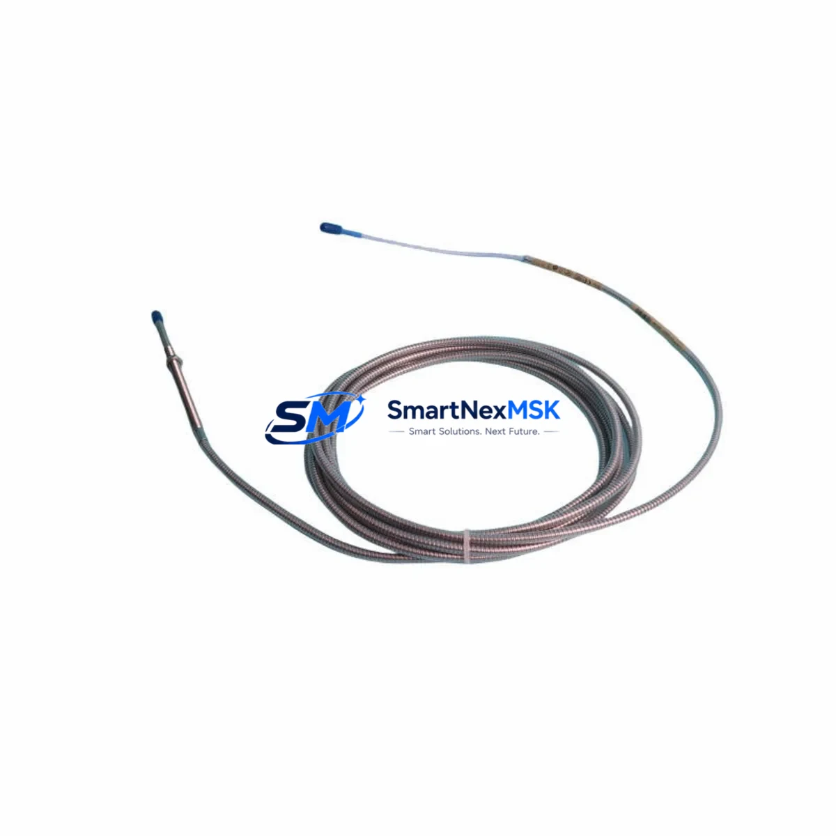
The Bently Nevada 330104-05-10-15-02-CN is a high-precision eddy-current proximity transducer engineered for the 3300 XL Series vibration monitoring platform. Designed to deliver reliable shaft displacement and radial vibration measurements in rotating machinery applications, this unit serves as a direct retrofit replacement for legacy 3300 Series transducers that have reached end-of-life or are no longer available through standard supply channels. Whether you are upgrading an aging turbine protection system, restoring a compressor monitoring rack, or migrating from an obsolete Bently Nevada 3300 standard-series configuration to the 3300 XL architecture, the 330104-05-10-15-02-CN provides the dimensional compatibility, signal output, and connector interface required for a smooth, low-risk transition.
This transducer operates as part of the complete 3300 XL proximity system, which includes the extension cable (typically the 330130 series) and the proximitor sensor (330180 series). When planning a retrofit, engineers must verify that the existing extension cable length matches the new transducer’s calibrated gap range. The 330104-05-10-15-02-CN is calibrated for a specific probe-to-proximitor combination, and substituting mismatched cable lengths will introduce scale factor errors that affect vibration amplitude readings. Always confirm the full system configuration — probe, cable, and proximitor — before finalizing the replacement order.
Upgrade Compatibility Table
| Parameter | Detail |
|---|---|
| Model | Bently Nevada 330104-05-10-15-02-CN |
| Series | 3300 XL Proximity Transducer System |
| Probe Tip Diameter | 5 mm (standard eddy-current tip) |
| Probe Length | 10 mm armored housing |
| Cable Length | 15 ft (4.57 m) integral cable |
| Connector Type | 02 — standard BNC-compatible proximitor connector |
| Target Material Compatibility | Steel, 4140 alloy, Inconel 718 (verify with application) |
| Installation Interface | M10 x 1 threaded housing, compatible with standard 3300 Series probe holders |
| Signal Output | –24 VDC bias, –200 mV/mil (–7.87 V/mm) scale factor |
| Communication Compatibility | Analog 4–20 mA via 3300 XL proximitor; integrates with System 1 and TDXnet monitoring networks |
| Replacement Recommendation | Direct drop-in for 330104-05-10-15-02 (non-CN) in CN-market installations |
| Commissioning Notes | Verify gap voltage (–10 VDC ±0.5 V at nominal gap), confirm OK relay status on proximitor module |
| Warranty | 12 Months from date of shipment |
Retrofit Planning for Existing Automation Systems
Successful integration of the 330104-05-10-15-02-CN into an existing machinery protection system requires a structured pre-installation review. Begin by auditing the current rack configuration. Most legacy installations use the 3500 Series rack or the older 3300 standard rack. If the host rack is a 3500/22M transient data interface or a 3500/42M proximitor I/O module, confirm that the proximitor input channel is configured for the 3300 XL probe scale factor. Mismatches between the proximitor module firmware and the probe calibration data will cause the System 1 software to flag false OK/Not OK transitions.
For installations using the 3300 XL 8-mm proximity transducer system (such as the 330780-50-00 or 330730-040-00-00 series) alongside the 5-mm 330104 series, ensure that the proximitor modules — typically the 330180-X1-05 or 330180-X1-CN variants — are matched to the correct probe diameter and cable length. Mixing 5-mm and 8-mm probes on the same proximitor will produce calibration errors that cannot be corrected through software offset alone.
Terminal wiring should be verified against the original I/O drawing. The 330104-05-10-15-02-CN uses a standard coaxial cable termination at the proximitor end. If the existing conduit run uses a 330130-080-00-00 extension cable, confirm that the total system cable length (probe integral cable plus extension) does not exceed the proximitor’s rated input range. For installations where the original wiring used a different connector standard, a 330940 series field-wireable connector may be required to maintain signal integrity.
When the retrofit involves migrating from a legacy 3300 standard-series monitoring system to a 3300 XL or 3500 Series platform, the engineering team must also review the HMI configuration. Operator displays built on the Bently Nevada System 1 platform will require tag remapping if the channel addresses change during the rack upgrade. Export the existing System 1 database before beginning any hardware swap, and verify that the new proximitor module addresses match the original channel assignments to avoid alarm setpoint migration errors.
Power supply capacity is another critical checkpoint. The 3300 XL proximitor system draws approximately 35 mA per channel at –24 VDC. If the control cabinet power supply — often a Bently Nevada 3500/15 power supply module or an equivalent third-party 24 VDC DIN-rail unit — is already near capacity due to added I/O expansion modules or communication gateway devices, a load calculation must be performed before adding new transducer channels. Insufficient supply headroom will cause intermittent OK relay dropout under load, which is frequently misdiagnosed as a probe or cable fault.
Downtime Control During System Migration
Minimizing unplanned downtime during a proximity transducer retrofit requires a phased replacement strategy. Where process conditions permit, perform the transducer swap during a scheduled maintenance window rather than a forced outage. Before removing the existing probe, document the current gap voltage reading at the proximitor terminal strip. This baseline value — typically between –9.5 VDC and –10.5 VDC for a correctly installed 5-mm probe — serves as the acceptance criterion for the replacement unit after installation.
If the machinery cannot be taken offline for the full duration of the replacement, consider using a spare channel on an adjacent 3500/42M or 3300 XL proximitor module to pre-wire and verify the new 330104-05-10-15-02-CN before transferring the active monitoring function. This parallel commissioning approach allows the control room to maintain continuous vibration monitoring on the critical machine train while the new transducer is being calibrated and verified in the field.
Protect the existing PLC or DCS program logic during the migration. If the vibration monitoring outputs feed into a GE Fanuc Series 90 PLC, a Siemens S7-300 safety interlock, or an ABB AC800M distributed control system via hardwired relay contacts, confirm that the OK relay output from the new proximitor module is correctly wired and that the interlock logic has been tested in bypass mode before returning the machine to service. Never assume that a replacement transducer will restore the OK relay state without a verified gap measurement and a confirmed proximitor power cycle.
After installation, perform a full channel functional test: apply a known displacement simulation using a calibration target or a certified gap-setting tool, verify the output voltage linearity across the measurement range, and confirm that the System 1 or TDXnet alarm setpoints are active and correctly scaled. Document the as-left gap voltage, the proximitor serial number, and the installation date for the maintenance record. This documentation supports the 12-month warranty claim process and provides the baseline for the next scheduled calibration interval.
Retrofit Support FAQ
Q1: Is the 330104-05-10-15-02-CN a direct replacement for the non-CN version (330104-05-10-15-02)?
Yes. The CN suffix designates the China-market configuration, which uses the same electrical specifications, probe tip geometry, and cable termination as the standard international version. The unit is electrically and mechanically interchangeable in all 3300 XL system installations. No firmware changes or scale factor adjustments are required when substituting the CN variant for the standard part number.
Q2: What wiring checks are required before powering up the replacement transducer?
Verify coaxial cable continuity from the probe connector to the proximitor terminal strip. Confirm that the shield drain wire is grounded at one end only (typically at the proximitor end) to prevent ground loop interference. Check that the –24 VDC supply to the proximitor module is within ±0.5 V of nominal before applying power. After power-up, measure the gap voltage at the proximitor output terminal and confirm it falls within the –9.5 to –10.5 VDC acceptance window at the installed gap distance.
Q3: How is compatibility with the 3500 Series rack verified before installation?
Confirm that the 3500/42M proximitor I/O module is configured for 5-mm probe input (not 8-mm). Check the module configuration in the Rack Configuration Software (RCS) and verify that the scale factor is set to –200 mV/mil. If the rack was previously configured for an 8-mm probe system such as the 330780 series, the RCS configuration must be updated and re-downloaded to the module before the new transducer is connected.
Q4: What does the 12-month warranty cover, and what is the claim process?
The 12-month warranty covers manufacturing defects in materials and workmanship from the date of shipment. It does not cover damage resulting from incorrect installation, overvoltage conditions, mechanical impact, or use outside the rated environmental specifications. To initiate a warranty claim, contact sales@smartnexmsk.com with the original order number, the unit serial number, and a description of the observed fault. Units must be returned in original or equivalent protective packaging. Replacement or repair will be completed within the agreed lead time following fault verification.
© 2026 SMARTNEXMSK. All rights reserved.
Original Source: https://smartnexmsk.com
Contact: sales@smartnexmsk.com | +86 18259474341


