Bently Nevada 330104-05-13-10-01-00 Retrofit-Ready Proximity Transducer for 3300 XL Control Systems
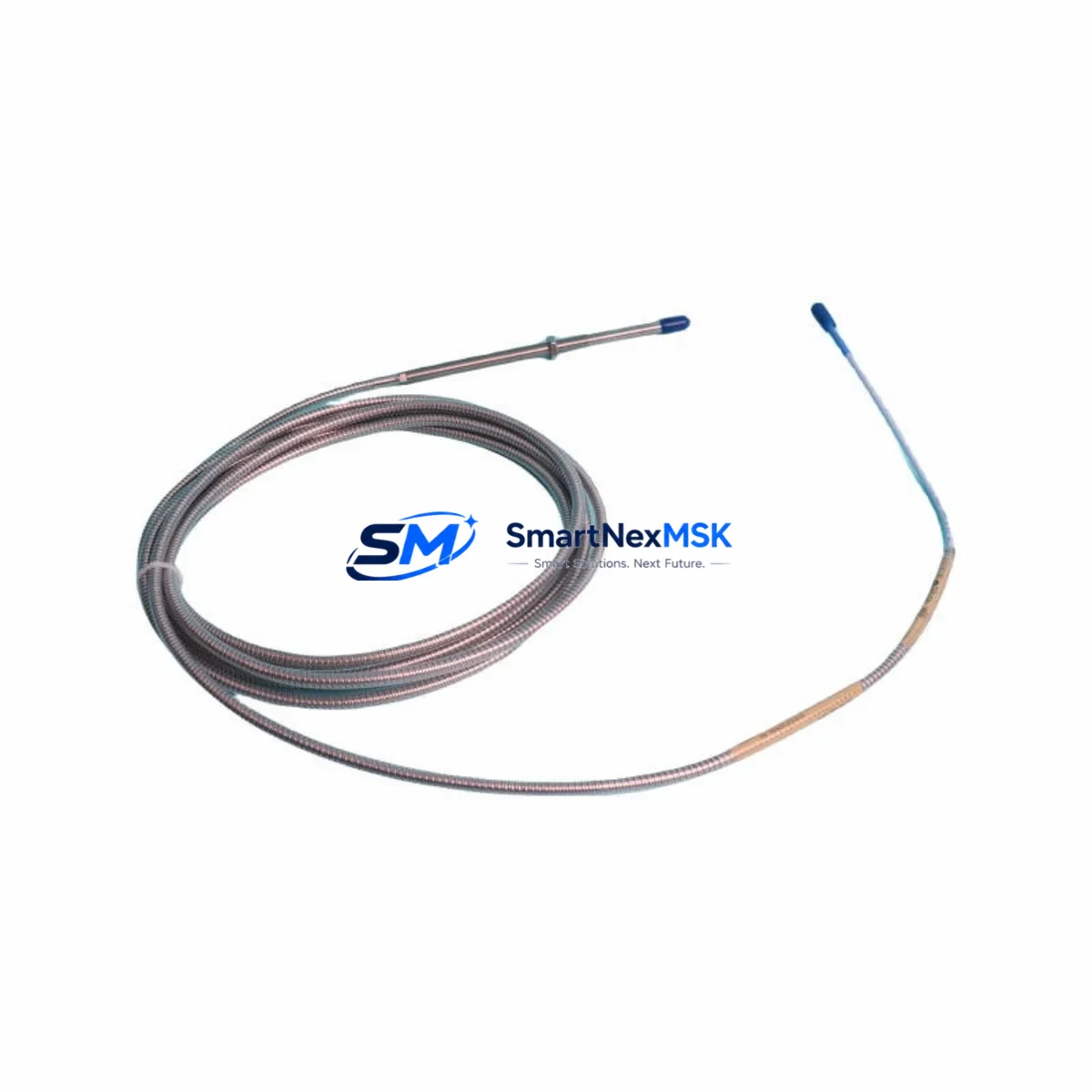
The Bently Nevada 330104-05-13-10-01-00 is an eddy current proximity transducer engineered for the 3300 XL Series vibration monitoring platform. As legacy rotating machinery protection systems reach end-of-service life, this module serves as a verified drop-in replacement for discontinued 3300 Series transducers, enabling smooth migration without redesigning the existing monitoring architecture. Whether you are upgrading a turbine protection panel, retrofitting a compressor train monitoring rack, or restoring a mothballed machine protection system, the 330104-05-13-10-01-00 delivers the dimensional, electrical, and signal compatibility required for a low-risk, minimum-downtime changeover.
This transducer is designed for use with the Bently Nevada 3300 XL 8mm Proximity Transducer System, operating on the standard Bently Nevada eddy current measurement principle. The 5-metre extension cable and 13-metre interconnect cable configuration (5m/13m) matches the most common field installation geometry found in legacy turbomachinery protection cabinets. The output signal range, sensitivity, and connector pinout are fully compatible with existing 3300 XL proximitor/seismic interface modules, eliminating the need to reconfigure signal conditioning cards or recalibrate gap voltage setpoints.
Upgrade Compatibility Table
| Parameter | 330104-05-13-10-01-00 (This Unit) | Legacy 3300 Series Reference |
|---|---|---|
| Series Platform | 3300 XL 8mm | 3300 / 3300 XL |
| Cable Configuration | 5m probe + 13m extension | 5m + 13m (standard) |
| Output Sensitivity | 7.87 V/mm (200 mV/mil) | 7.87 V/mm (200 mV/mil) |
| Supply Voltage | −24 VDC (nominal) | −24 VDC |
| Connector Type | Standard BN coaxial | Standard BN coaxial |
| Thread / Mounting | M10 × 1 probe tip | M10 × 1 |
| Communication Protocol | Analogue (4–20 mA / voltage) | Analogue |
| Replacement Recommendation | Direct drop-in for 330104 family | Verified compatible |
| Commissioning Note | Verify gap voltage at installation | Standard BN gap procedure |
| Warranty | 12 Months | — |
Retrofit Planning for Existing Automation Systems
Successful integration of the 330104-05-13-10-01-00 into an existing turbomachinery protection system requires a structured pre-installation review. Begin by auditing the proximitor housing — typically a Bently Nevada 3300 XL Proximitor/Seismic Interface Module — to confirm the existing gap voltage is within the −10 VDC to −18 VDC linear range before removing the old transducer. Document the as-found gap reading so the replacement can be set to the same operating point, preserving alarm and danger setpoints without requiring a full system re-engineering review.
Terminal wiring follows the standard three-conductor coaxial arrangement used across the 3300 XL platform. The shield, centre conductor, and return path must be verified against the existing field wiring diagram before energising the circuit. In installations where the extension cable routes through conduit shared with power conductors, confirm that the cable jacket rating is appropriate for the ambient temperature and that the coaxial shield is grounded at one end only, consistent with Bently Nevada field wiring practice.
For systems that also include a Bently Nevada 3500/42M Proximitor I/O Module or a 3500/40M Proximitor/Seismic Monitor, the channel configuration in the 3500 rack does not require modification when replacing a like-for-like 330104-family transducer. The rack’s internal scaling and OK limit logic will continue to function without a firmware update or rack reconfiguration, which significantly reduces the scope of the management of change (MOC) documentation required for the swap.
Where the protection system interfaces with a DCS — such as a Honeywell Experion PKS, Emerson DeltaV, or ABB System 800xA — the 4–20 mA or voltage output from the proximitor feeds the DCS analogue input card directly. No changes to the DCS I/O configuration, scaling, or alarm logic are required, provided the replacement transducer is installed at the same gap distance as the original. Confirm with the DCS historian that the vibration trend tag continues to log correctly after the swap by comparing pre- and post-replacement baseline readings.
In multi-channel protection racks, it is common practice to replace transducers in pairs (X and Y radial channels) to maintain consistent sensitivity and gap characteristics across both measurement planes. If the companion channel uses a 330104-00-13-10-01-00 or 330104-05-08-10-01-00 variant, verify that the cable length and sensitivity specification match before ordering. The 3300 XL Proximitor module will flag an OK fault if the two channels present significantly different gap voltages, which can trigger a spurious trip if not managed during the changeover window.
For installations that include a Bently Nevada 3300 XL 11 mm Proximity Transducer System alongside the 8 mm system, ensure that the correct probe diameter is ordered — the 330104 family is specific to the 8 mm probe geometry and is not interchangeable with the 330175 or 330180 series used in 11 mm and 14 mm applications. Similarly, if the machine protection system includes a Bently Nevada 3500/15 Power Supply Module, confirm that the rack power budget accommodates the transducer system load before adding channels during an expansion project.
Downtime Control During System Migration
Minimising unplanned downtime during a proximity transducer replacement requires pre-staging all materials before the maintenance window opens. Confirm that the 330104-05-13-10-01-00 unit has been bench-tested against a reference target at the correct gap distance and that the output voltage falls within the published linear range. This pre-shipment functional test, which is included as part of the 12-month warranty coverage, eliminates the risk of installing a non-conforming unit and discovering the fault only after the machine is returned to service.
During the replacement, maintain the existing cable routing and avoid disturbing the extension cable connector at the proximitor housing unless the connector shows signs of corrosion or mechanical damage. Re-torque the probe to the manufacturer’s specified value and re-check the gap with a feeler gauge or by monitoring the DC gap voltage at the proximitor output terminal. Record the as-left gap voltage in the maintenance management system (CMMS) to establish a new baseline for future condition monitoring trending.
If the machine cannot be taken offline for the replacement, consult the site’s hot-work and bypass procedures. Many 3500-series racks support channel bypass via the 3500 Rack Configuration Software, allowing a single channel to be placed in bypass mode while the machine remains in service. This approach preserves the protection function on the remaining channels and allows the transducer swap to be completed without a full machine trip, subject to site safety and regulatory approval.
After re-energising the channel, allow the proximitor output to stabilise for a minimum of 15 minutes before releasing the bypass and returning the channel to normal protection mode. Compare the post-replacement vibration baseline against the historical trend to confirm that the new transducer is tracking correctly. Any deviation greater than 10% from the pre-replacement baseline should be investigated before the machine is returned to full load.
Retrofit Support FAQ
Q1: Is the 330104-05-13-10-01-00 a direct replacement for the original Bently Nevada 330104 series transducer?
Yes. The 330104-05-13-10-01-00 is a verified drop-in replacement for the 330104 family of 8 mm eddy current proximity transducers used in the 3300 XL platform. The probe geometry, cable configuration, connector type, and output sensitivity are identical to the original specification, requiring no modification to the proximitor housing, terminal wiring, or rack configuration.
Q2: What commissioning checks are required after installation?
After installation, verify the DC gap voltage at the proximitor output terminal. The linear range for the 3300 XL 8 mm system is −10 VDC to −18 VDC, with a nominal operating gap of approximately −12 VDC. Confirm that the OK relay is energised and that the vibration channel is reading a stable baseline before releasing any bypass and returning the channel to normal protection mode.
Q3: Does the replacement affect the DCS or HMI configuration?
No. Because the 330104-05-13-10-01-00 maintains the same output sensitivity and signal range as the original transducer, the DCS analogue input scaling, alarm setpoints, and HMI display tags do not require modification. The DCS historian will continue to log the vibration trend tag without interruption, provided the replacement is installed at the same gap distance as the original unit.
Q4: What does the 12-month warranty cover?
The 12-month warranty covers manufacturing defects, component failure under normal operating conditions, and output signal non-conformance relative to the published specification. Each unit undergoes a pre-shipment functional test at the correct gap distance to verify output voltage, OK relay operation, and cable continuity. Warranty claims are supported by SMARTNEXMSK with direct technical assistance and expedited replacement dispatch to minimise machine downtime.
© 2026 SMARTNEXMSK. All rights reserved.
Original Source: https://smartnexmsk.com
Contact: sales@smartnexmsk.com | +86 18259474341


