Bently Nevada 330104-05-13-10-02-05 Spare 3300 XL NSv: Precision Replacement for Vibration Monitoring Systems
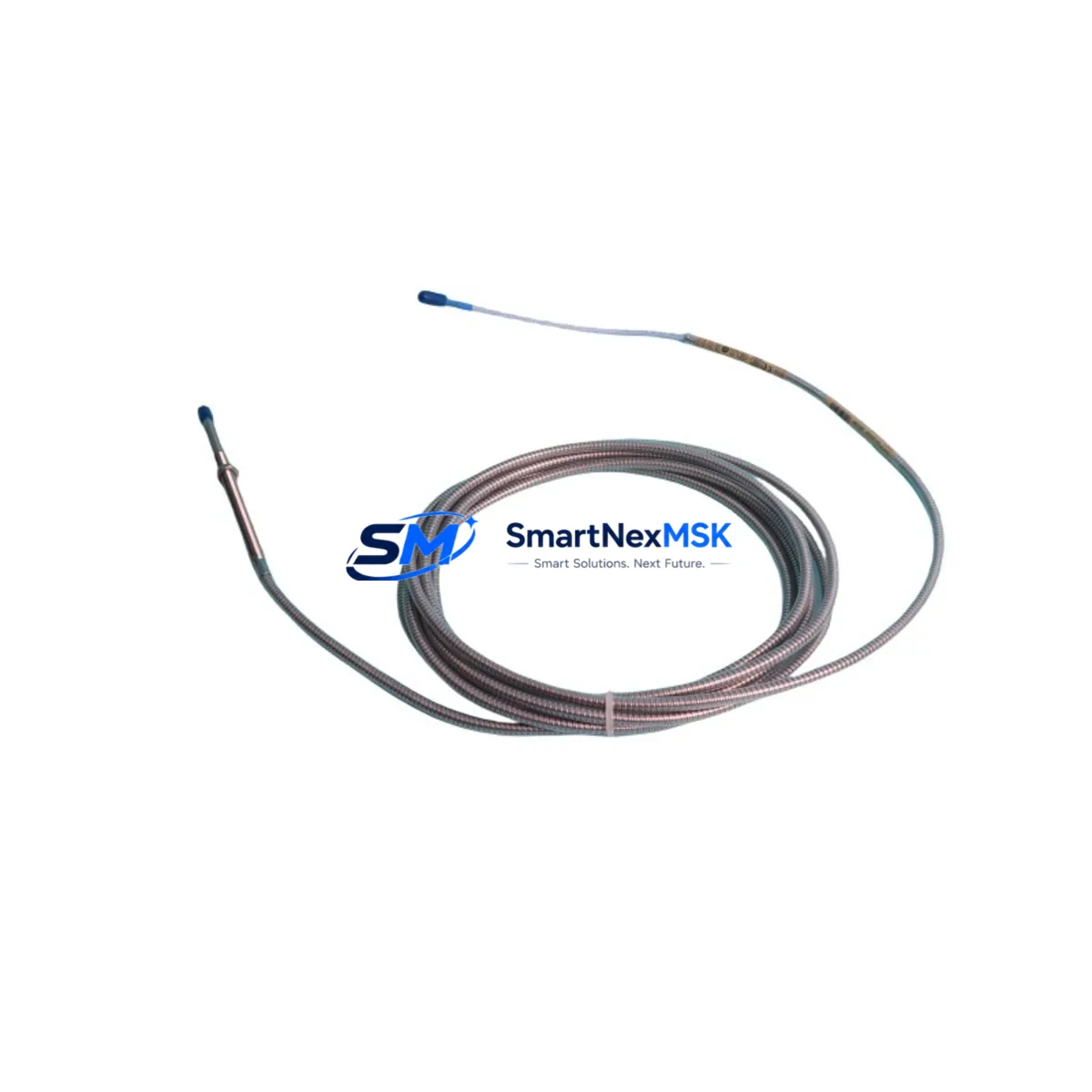
The Bently Nevada 330104-05-13-10-02-05 is an original proximity transducer engineered for the 3300 XL NSv (Non-contact Shaft Vibration) monitoring system — one of the most widely deployed continuous vibration monitoring platforms in rotating machinery protection. Designed for turbines, compressors, pumps, and gearboxes operating in critical process environments, this transducer delivers the sub-micron displacement resolution and signal linearity that plant reliability engineers depend on for early fault detection and unplanned downtime prevention.
Sourced as an original manufacturer spare, each unit undergoes pre-shipment functional verification covering output voltage linearity, gap sensitivity, cable continuity, and connector integrity. A 12-month warranty is included with every shipment, providing procurement and maintenance teams with the confidence required for long-term spare parts planning.
Spare Maintenance Table
| Parameter | Specification / Value |
|---|---|
| SKU / Part Number | 330104-05-13-10-02-05 |
| Brand | Bently Nevada |
| Series | 3300 XL NSv Proximity Transducer System |
| Product Type | Eddy-Current Proximity Transducer |
| Measurement Range | 0–200 mil (0–5.08 mm) typical |
| Output Sensitivity | 200 mV/mil (7.87 V/mm) |
| Supply Voltage | −24 VDC (nominal), via Proximitor® driver |
| Operating Temperature | −35°C to +120°C (probe tip) |
| Cable Length | 5 m (extension cable 330130 series compatible) |
| Connector Type | Coaxial, compatible with 3300 XL driver/Proximitor |
| Compatibility | 3300 XL NSv Proximitor® 330180 / 330181 series |
| Target Material | Steel / Stainless Steel shaft surfaces |
| Installation | Radial or axial mounting per API 670 guidelines |
| Application | Turbines, compressors, pumps, gearboxes, motors |
| Certification | CE, FM, ATEX (refer to original datasheet) |
| Warranty | 12 Months from shipment date |
| Condition | Original spare — pre-shipment tested |
Maintenance Planning for Continuous Operation
When replacing the 330104-05-13-10-02-05 proximity transducer during a planned outage or emergency callout, a disciplined maintenance engineer will treat the transducer as one node in a complete measurement chain — not an isolated component. The 3300 XL NSv system relies on tight coordination between the probe, the extension cable (typically a 330130-series armored cable), and the Proximitor® driver module (330180 or 330181) to maintain calibrated gap voltage and signal linearity. If the transducer is being replaced due to drift or signal loss, the extension cable and driver should be inspected simultaneously, as connector corrosion or cable shield damage frequently causes identical symptoms.
At the rack level, the 3300 XL monitor card — often a 3300/16 or 3300/20 series I/O module — should be checked for firmware revision compatibility and channel calibration offsets before the new transducer is commissioned. Maintenance teams operating Bently Nevada System 1 condition monitoring software should verify that the new transducer’s sensitivity constant is correctly entered in the channel configuration to avoid false alarm thresholds.
For control cabinet inspections concurrent with this replacement, engineers should audit the 24 VDC power supply rail feeding the Proximitor® drivers, as voltage sag below −22 VDC will cause measurement errors that mimic transducer failure. Terminal blocks on the signal wiring — particularly in high-vibration environments — should be re-torqued and inspected for fretting corrosion. If the plant runs a redundant monitoring architecture, the paired channel’s transducer (often mounted 90° offset for XY vibration measurement) should be inspected at the same time to maintain balanced system health.
For facilities managing aging 3300 XL installations alongside newer 3500 series racks, it is worth confirming that the correct Proximitor® driver is matched to the transducer gap range — cross-series mismatches are a common source of commissioning errors during emergency replacements. Spare parts planners should also maintain buffer stock of the 330130 extension cable and the 330180 Proximitor® driver alongside the 330104-05-13-10-02-05 transducer to enable complete chain replacement without secondary procurement delays.
In DCS-integrated environments where the vibration signal feeds a 4–20 mA transmitter or a signal isolator before entering the process historian, the isolator module and its loop power supply should be verified as part of the same work order. This prevents a scenario where a successfully replaced transducer is masked by a downstream signal conditioning fault that was pre-existing but undetected.
Site Replacement Workflow
Step 1 — Isolation and Lockout: Follow plant LOTO procedures. Confirm the monitored shaft is at rest and the Proximitor® driver channel is de-energized before disconnecting the transducer coaxial connector.
Step 2 — Gap Measurement: Before removing the old transducer, record the installed gap distance using a feeler gauge or the existing DC gap voltage reading from the monitor card. The target gap for the 330104-05-13-10-02-05 is typically 50 mil (1.27 mm) for standard steel targets — confirm against the original installation record.
Step 3 — Transducer Removal: Unscrew the transducer from its mounting bracket. Inspect the bracket threads and locknut for wear. Replace the locknut if thread engagement is compromised.
Step 4 — New Transducer Installation: Thread the 330104-05-13-10-02-05 into the bracket. Set gap to the recorded value. Secure with locknut. Reconnect the extension cable coaxial connector — ensure the connector is fully seated and the coupling nut is finger-tight plus one-quarter turn.
Step 5 — Energize and Verify: Re-energize the Proximitor® driver. Measure DC gap voltage at the monitor card input. Confirm the reading falls within the calibrated range (typically −10 VDC ±1 VDC at nominal gap). Clear any latched alarms in the 3300 XL monitor or System 1 software.
Step 6 — Functional Test: With the shaft rotating at operating speed, confirm vibration amplitude readings are within baseline historical values. Log the replacement in the CMMS with the new transducer serial number and gap setting.
This workflow minimizes downtime, ensures measurement chain integrity, and provides a documented audit trail for reliability and compliance reviews.
Spare Parts Support FAQ
Q1: Is the 330104-05-13-10-02-05 a direct drop-in replacement for older 3300 series transducers?
The 330104-05-13-10-02-05 is designed for the 3300 XL NSv system. Compatibility with earlier 3300 (non-XL) Proximitor® drivers depends on the driver revision. Always verify the Proximitor® model number (330180 vs. 330100 series) before ordering. Our technical team can assist with cross-reference confirmation prior to shipment.
Q2: What pre-shipment testing is performed on each unit?
Every 330104-05-13-10-02-05 unit is tested for output voltage linearity across the full gap range, coaxial connector continuity, cable shield integrity, and physical inspection of the probe tip and body. A test report is available upon request. The 12-month warranty covers functional failure under normal operating conditions.
Q3: How should this transducer be stored as a long-term spare?
Store in the original packaging or an anti-static, moisture-controlled environment at 15–30°C. Avoid coiling the cable tightly — maintain a minimum bend radius of 50 mm. Inspect the coaxial connector for oxidation annually. Shelf life under proper storage conditions exceeds 5 years without performance degradation.
Q4: What is the lead time and shipping process?
In-stock units ship within 1–3 business days. Each shipment includes a packing list, test confirmation, and warranty certificate. Express international shipping is available for emergency maintenance situations. Contact sales@smartnexmsk.com or +86 18259474341 for urgent requirements.
© 2026 SMARTNEXMSK. All rights reserved.
Original Source: https://smartnexmsk.com
Contact: sales@smartnexmsk.com | +86 18259474341


