Bently Nevada 330104-05-13-50-02-00 Retrofit-Ready Proximity Probe for 3300 XL Control Systems
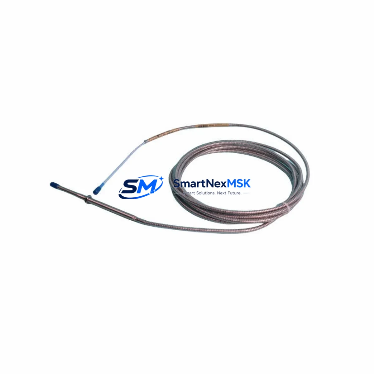
The Bently Nevada 330104-05-13-50-02-00 is an 8mm eddy current proximity probe engineered for direct retrofit and drop-in replacement within legacy 3300 XL Series vibration monitoring systems. As rotating machinery protection systems age and original spare parts become increasingly scarce, this probe provides a verified, specification-matched solution for engineers managing planned upgrades, emergency replacements, and long-term system modernization programs. Whether you are restoring a turbine protection loop, upgrading a compressor monitoring rack, or migrating from an obsolete 3300 Series platform to a current-generation Bently Nevada System 1 architecture, the 330104-05-13-50-02-00 delivers the signal integrity, mechanical compatibility, and installation confidence your application demands.
Each unit ships pre-tested against Bently Nevada factory output specifications, with sensitivity verified at -7.87 V/mm (−200 mV/mil) and a linear range confirmed across the full operating gap. The probe integrates directly with the 3300 XL Proximitor® sensor, including the 330180 and 330130 series extension cables, without requiring field rewiring or connector modification. For retrofit projects where the existing cable infrastructure must be preserved, this compatibility eliminates one of the most time-consuming variables in a planned outage window.
Upgrade Compatibility Table
| Parameter | Detail |
|---|---|
| SKU / Part Number | 330104-05-13-50-02-00 |
| Probe Diameter | 8 mm |
| Cable Length | 5 m (integral) |
| Connector Type | Standard Bently Nevada coaxial, compatible with 330130 / 330180 extension cables |
| Proximitor Compatibility | 3300 XL 8mm Proximitor® Sensor (330180 series) |
| Replaces / Supersedes | 330104-05-12-50-02-00, 330104-05-13-50-01-00, legacy 3300 Series 8mm probes |
| System Compatibility | Bently Nevada 3300 XL, 3500 Series (with appropriate Proximitor), System 1 integration |
| Output Sensitivity | −7.87 V/mm (−200 mV/mil) |
| Installation Requirement | Standard 3/8-24 UNF thread mount; no bracket modification required |
| Communication / Signal | Analog voltage output; compatible with 3500/40M and 3500/42M monitor modules |
| Retrofit Recommendation | Replace probe and verify gap setting (1.0–2.5 mm typical); re-zero in System 1 or rack display |
| Commissioning Note | Confirm Proximitor supply voltage (−24 VDC nominal) before energizing; validate OK/NOT OK relay logic |
| Warranty | 12 Months from date of shipment |
Retrofit Planning for Existing Automation Systems
A successful retrofit of the 330104-05-13-50-02-00 into an operating plant environment requires systematic pre-outage planning. Begin by auditing the existing rack configuration. In a typical 3500 Series protection rack, the probe signal is routed through a 330180 Proximitor sensor mounted in the field junction box, then carried via a 330130 extension cable back to the 3500/40M or 3500/42M monitor module installed in the 19-inch rack. Confirm that the Proximitor supply voltage rail—nominally −24 VDC—is within tolerance before disconnecting the old probe. A degraded power supply module in the rack can mask probe faults and produce misleading gap readings during commissioning.
For sites running a mixed 3300 XL and 3500 Series architecture, the probe is mechanically and electrically interchangeable across both platforms, provided the correct Proximitor model is in place. If the existing Proximitor is a legacy 3300 XL 8mm unit showing signs of drift or intermittent OK relay chatter, consider replacing it alongside the probe during the same outage window. Pairing a new 330104-05-13-50-02-00 probe with a refurbished or replacement 330180 Proximitor sensor eliminates the most common sources of nuisance trips in aging eddy current loops.
Terminal wiring at the field junction box follows the standard Bently Nevada three-conductor coaxial convention: center conductor (signal), inner shield (return), and outer shield (case ground). Verify continuity and insulation resistance on the extension cable before reconnecting. If the 330130 extension cable shows insulation degradation—common in high-temperature or chemically aggressive environments—replace it as part of the retrofit rather than risk a latent fault after startup. I/O mapping at the 3500/40M monitor module does not change when substituting a same-specification probe; channel address, alert setpoints, and danger setpoints carry over without reprogramming.
For plants migrating toward a System 1 condition monitoring platform, the 330104-05-13-50-02-00 is fully compatible with System 1 data acquisition nodes that accept standard Proximitor analog inputs. No driver update or firmware change is required at the System 1 server. HMI trend displays and alarm faceplates configured for the original probe channel will continue to function without modification, preserving operator familiarity and reducing the risk of configuration errors during the transition period.
Where the retrofit scope extends to I/O expansion—for example, adding a second radial vibration channel on a bearing that was previously unmonitored—the 3500/40M dual-channel monitor module can accommodate the additional probe without requiring a new rack slot. Coordinate the I/O address assignment with the control system integrator before the outage to avoid conflicts with existing channel maps in the DCS or safety instrumented system. If the plant runs a Rockwell Automation ControlLogix or CompactLogix PLC for auxiliary machinery control, confirm that the analog input card scaling matches the −200 mV/mil sensitivity of the new probe before closing the loop.
Downtime Control During System Migration
Minimizing unplanned downtime during a proximity probe retrofit depends on three disciplines: pre-staging, parallel verification, and a structured return-to-service sequence. Pre-stage the 330104-05-13-50-02-00 by bench-testing the probe and Proximitor pair before the outage begins. Apply the correct gap using a non-conductive feeler gauge or a calibrated gap tool, and confirm the Proximitor output voltage falls within the linear range before the assembly leaves the workshop. This eliminates the most common cause of extended commissioning time—discovering a faulty component after the machine is already isolated.
During the outage, photograph the existing terminal wiring at the field junction box and the rack before disconnecting anything. Retain the original probe gap measurement if it was recorded in the maintenance management system; it provides a baseline for the new installation. After installing the 330104-05-13-50-02-00 and reconnecting the 330130 extension cable, power up the Proximitor and measure the output voltage at the monitor module input terminals before enabling the channel. A reading within the expected linear range confirms mechanical installation is correct and the cable is intact.
Preserve the original program logic in the 3500 Series rack or the connected PLC by exporting a configuration backup before the outage. The Bently Nevada 3500 rack configuration software allows a full channel-by-channel export that can be restored in minutes if a configuration error occurs during commissioning. For System 1 integrations, snapshot the current trend data and alarm history before the outage so that post-retrofit baseline comparisons are meaningful. Once the machine is back online, monitor the first 30 minutes of operation closely—gap stability, OK relay status, and vibration trend trajectory are the three indicators that confirm a successful retrofit without requiring an additional outage.
Retrofit Support FAQ
Q1: Is the 330104-05-13-50-02-00 a direct drop-in replacement for the 330104-05-12-50-02-00?
Yes. The two part numbers share identical mechanical dimensions, connector type, and output sensitivity. The suffix difference reflects a minor revision in the cable jacket material. No wiring changes, bracket modifications, or Proximitor reconfiguration are required when substituting one for the other.
Q2: What gap setting should I use during installation?
The recommended installation gap for an 8mm Bently Nevada probe on a standard steel target is 1.0–2.5 mm (approximately 40–100 mil). The optimal gap for maximum linear range is typically 1.27 mm (50 mil), which places the Proximitor output at approximately −10.0 VDC. Confirm the final gap against the Proximitor output voltage rather than relying solely on a mechanical measurement.
Q3: Will this probe work with my existing 3500/40M monitor module without reprogramming?
Yes, provided the replacement probe has the same sensitivity specification (−200 mV/mil) as the original. The 3500/40M stores alert and danger setpoints in engineering units (e.g., µm pk-pk or mil pk-pk), not in raw voltage, so a same-sensitivity replacement does not alter the effective trip thresholds. Verify the channel OK status and perform a functional test of the alert and danger relay outputs before returning the machine to service.
Q4: What does the 12-month warranty cover, and how is it processed?
The 12-month warranty covers manufacturing defects, premature output drift beyond published specification, and connector or cable integrity failures under normal operating conditions. Warranty claims are processed by contacting sales@smartnexmsk.com with the order reference, installation date, and a description of the observed fault. Units confirmed defective are replaced or credited at our discretion. The warranty period begins on the date of shipment from our facility.
© 2026 SMARTNEXMSK. All rights reserved.
Original Source: https://smartnexmsk.com
Contact: sales@smartnexmsk.com | +86 18259474341


