Bently Nevada 330104-06-12-10-02-00 3300 XL Retrofit Probe: Compatible Modernization & Smooth System Upgrade
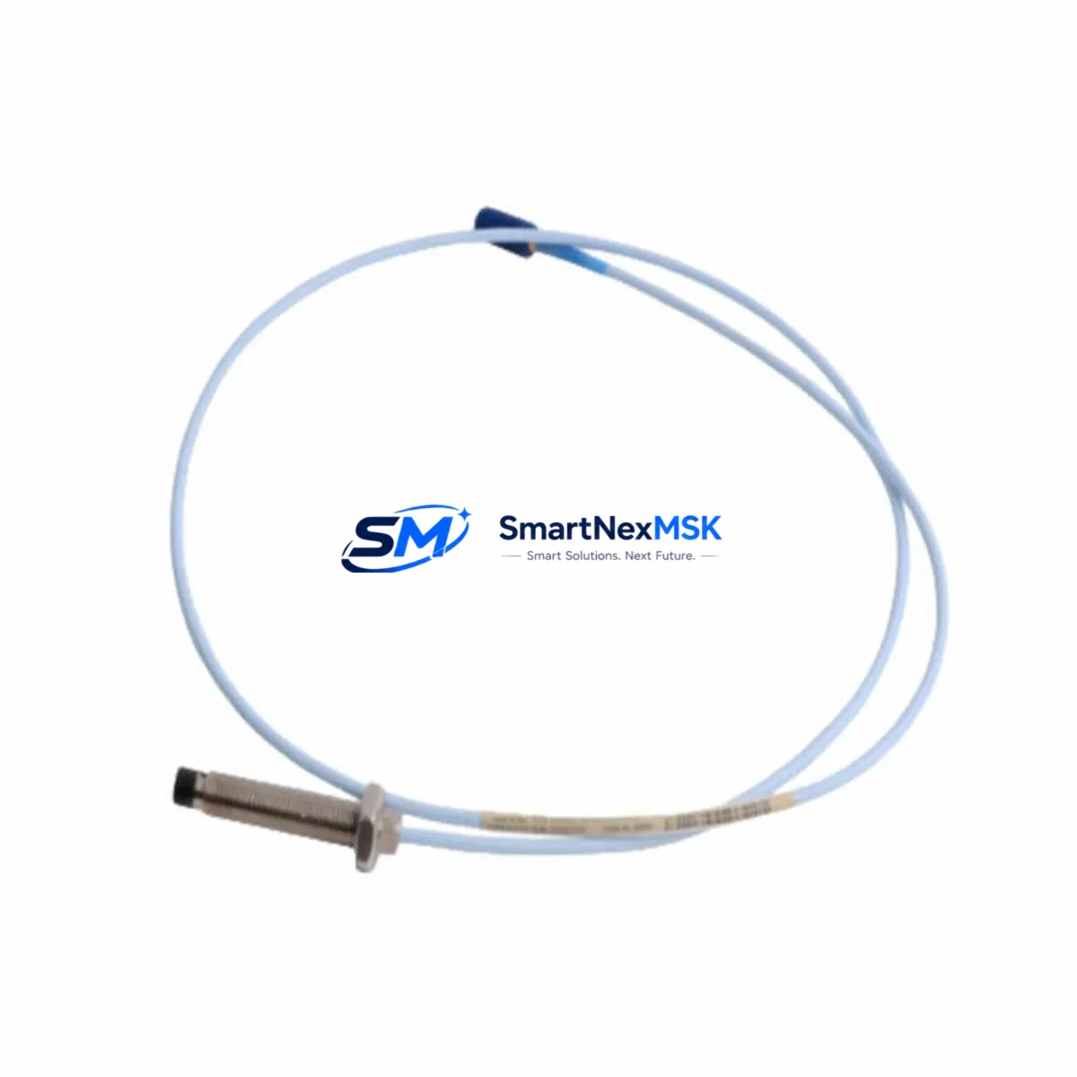
The Bently Nevada 330104-06-12-10-02-00 is an 8mm proximity probe engineered for the 3300 XL Series continuous vibration monitoring system. As legacy machinery protection systems age and OEM support windows close, this probe remains one of the most frequently specified retrofit components in turbine, compressor, and pump train monitoring upgrades. Whether you are replacing a failed sensor on a running production line, modernizing a legacy 3300 Series rack to 3300 XL architecture, or commissioning a new monitoring loop on an existing machine train, the 330104-06-12-10-02-00 delivers verified electrical and mechanical compatibility with minimal re-engineering effort.
This unit ships fully tested against Bently Nevada factory electrical specifications, including gap voltage linearity, sensitivity (200 mV/mil nominal), and frequency response. Each probe is paired with a matched extension cable and a 3300 XL proximitor/driver module to form a complete eddy-current sensing chain. Before installation, engineers should confirm that the existing proximitor — typically a 330180 or 330130 series driver — is calibrated for 8mm probe geometry. Mismatched probe-driver combinations are the leading cause of false trip events during retrofit commissioning.
Upgrade Compatibility Table
| Parameter | 330104-06-12-10-02-00 (This Unit) | Legacy 3300 Series Equivalent | Retrofit Notes |
|---|---|---|---|
| Probe Diameter | 8 mm | 8 mm | Direct mechanical fit; no bore modification required |
| Cable Length | 6 in (integral) | Varies | Match extension cable to total system length requirement |
| Extension Cable | 330130-080-00-00 (typical) | 330130 series | Verify total cable length ≤ system spec; re-terminate if needed |
| Driver / Proximitor | 330180-X1-05 / 330180-X1-CN | 330130 / 330180 series | Confirm 8mm calibration curve loaded in driver |
| Supply Voltage | −24 VDC (nominal) | −24 VDC | Verify rack power supply capacity before adding channels |
| Output Signal | −2 VDC to −18 VDC (gap range) | Same | No signal conditioning change required at monitor card |
| Monitor Card Interface | 3300/16 or 3300/20 monitor | 3300/16 / 3300/20 | Confirm I/O terminal block wiring map before re-termination |
| Communication Protocol | Analog (4–20 mA / voltage) | Analog | No protocol migration required; DCS analog input card compatible |
| Installation Standard | API 670 compliant | API 670 | No change to machinery protection standard |
| Warranty | 12 Months from shipment date | Covers electrical performance and mechanical integrity | |
Retrofit Planning for Existing Automation Systems
A successful retrofit of the 330104-06-12-10-02-00 into an operating machinery protection system requires a structured pre-outage engineering review. The following workflow reflects best practice for sites running Bently Nevada 3300 XL racks integrated with a DCS or safety instrumented system.
Power Budget Verification: Begin by auditing the 3300 XL rack’s power supply module — commonly a 3300/05 or 3300/10 power supply card. Each proximity probe channel draws approximately 25–35 mA from the −24 VDC bus. If you are adding channels during a rack expansion, confirm that the total channel count does not exceed the power supply’s rated output. Overloaded power supplies cause intermittent channel dropouts that are difficult to distinguish from genuine vibration events.
Terminal Block and Wiring Adaptation: The 330104-06-12-10-02-00 uses a standard Bently Nevada three-conductor shielded cable scheme: shield drain, signal (−), and common. When replacing an older 3300 Series probe, compare the existing terminal block wiring diagram against the 3300 XL I/O termination drawing. In many installations, the existing 3300/20 monitor card terminal blocks accept the new probe wiring without modification, but shield grounding practice must be verified — single-point grounding at the rack end is mandatory to prevent ground loop interference.
Backplane and Rack Interface: The 3300 XL system uses a dedicated backplane that routes power and communication between the 3300/16 or 3300/20 monitor cards and the system’s communication gateway — typically a 3500/92 or 3500/94 Ethernet/Serial interface module if the site has migrated to a 3500 Series rack. If your retrofit involves a mixed 3300/3500 architecture, confirm that the monitor card firmware version supports the probe sensitivity constant for the 330104-06-12-10-02-00. Firmware mismatches between the monitor card and the System 1 software database are a common source of incorrect engineering unit display.
Module Addressing and Channel Configuration: Each proximity probe channel in the 3300 XL rack is addressed by its physical slot position. After installing the replacement probe, verify the channel address in the rack configuration software matches the DCS tag database. Sites using Emerson System 1 Evolution or System 1 Condition Monitoring software should update the probe serial number and calibration date in the asset database to maintain audit trail continuity. If the site uses a 3500/22M transient data interface, confirm that the new probe’s gap voltage at the operating air gap (typically 1.0–1.5 mm for shaft proximity) falls within the monitor’s configured OK limits.
Program and Logic Compatibility: For sites where the 3300 XL rack feeds a safety PLC — such as a Triconex TRICON or a Rockwell Automation GuardLogix — the analog input scaling in the safety logic must be verified against the new probe’s sensitivity. A 200 mV/mil sensitivity probe feeding a 4–20 mA transmitter card requires the same engineering unit conversion as the original probe, but any change in cable length or driver model can shift the effective sensitivity by 1–3%, which may require a setpoint review with the process safety engineer.
HMI and Operator Display: If the vibration data is displayed on a Wonderware InTouch, FactoryTalk View, or Ignition SCADA screen, confirm that the tag name and engineering unit label in the HMI project match the updated DCS configuration. Probe replacements that change the measurement range or sensitivity constant can cause HMI trend displays to show a step change at the moment of cutover, which may trigger nuisance alarms in the historian.
Communication Link Integrity: Sites that use Modbus RTU or Modbus TCP to transmit vibration data from the 3300 XL gateway to a plant historian or DCS should verify that the register map for the replaced channel is unchanged after the retrofit. If the rack configuration was re-downloaded during the probe replacement, confirm that the Modbus register assignments were not re-ordered by the configuration software.
Downtime Control During System Migration
Minimizing unplanned downtime is the primary constraint in any proximity probe retrofit on a running machine train. The following approach is recommended for sites that cannot take an extended outage.
Hot-Standby Channel Strategy: Where the 3300 XL rack has a spare channel available, pre-wire and configure the replacement 330104-06-12-10-02-00 on the spare channel before the outage window. This allows the new probe to be verified electrically — gap voltage, OK relay status, and signal noise floor — while the machine is still running on the original channel. At the moment of cutover, the DCS operator switches the active channel reference in the control narrative, and the outage is limited to the physical probe swap at the machine.
Preserving Original Program Logic: Before any rack configuration download, export and archive the existing rack configuration file from the Bently Nevada rack configuration software. This file contains all setpoint values, OK limits, danger limits, and channel enable/disable states. If the retrofit introduces a configuration error, the archived file allows a full restore in under five minutes, preventing an extended troubleshooting outage. The same discipline applies to the DCS: export the relevant controller program revision from the Rockwell Studio 5000 or Siemens TIA Portal project before making any analog input scaling changes.
Field Commissioning Sequence: After the physical probe installation, follow this commissioning sequence to maintain control continuity: (1) Verify gap voltage at the proximitor output with the machine at rest — target −10 VDC ±0.5 VDC for a 1.0 mm air gap. (2) Confirm OK relay energized at the monitor card. (3) Verify engineering unit readout at the DCS operator station matches the expected baseline vibration level. (4) Release the channel from bypass and monitor for 15 minutes before returning the machine to full load. This sequence ensures that any wiring or configuration error is caught before the machine is exposed to full operating vibration levels, protecting both the new probe and the machine itself.
Inventory and Lead Time Management: To avoid extended outages caused by probe lead time, maintain a minimum of one spare 330104-06-12-10-02-00 per machine train in your site spare parts inventory. Our stock is available for same-day dispatch on confirmed orders, with DHL Express and FedEx International Priority options for urgent requirements. All units ship with a 12-month warranty certificate and a factory test report.
Retrofit Support FAQ
Q1: Is the 330104-06-12-10-02-00 a direct drop-in replacement for the older Bently Nevada 330104-06-12-10-00 or 330104-06-12-10-01 variants?
A: Yes. The -02-00 suffix designates the current production revision. It is electrically and mechanically interchangeable with earlier -00 and -01 suffix variants in the same 330104 family. No wiring changes or driver recalibration are required when replacing an earlier suffix revision with this unit. Confirm the probe body thread size (M10×1.0) and integral cable length (6 inches) match your installation before ordering.
Q2: Do I need to recalibrate the 330180 proximitor driver after installing this replacement probe?
A: Not typically. The 330180 series driver is factory-calibrated for the 8mm probe geometry and the standard 200 mV/mil sensitivity curve. If the replacement probe is the same model as the original, no recalibration is required. However, if the site has not performed a system calibration check in more than 24 months, we recommend verifying the gap voltage linearity across the full measurement range (0.25 mm to 2.25 mm) using a calibrated gap simulator before returning the channel to service.
Q3: What wiring changes are required when retrofitting this probe into a rack that previously used a 3300 Series (non-XL) monitor card?
A: The 3300 XL monitor cards use the same three-conductor wiring scheme as the original 3300 Series cards, so the field wiring from the junction box to the rack terminal block is typically unchanged. The primary difference is the terminal block connector type on the monitor card front panel. Verify that the existing field cable connector is compatible with the 3300 XL card’s terminal block before the outage. If the connector type differs, allow 30–60 minutes for re-termination in the outage plan.
Q4: What does the 12-month warranty cover, and what is the process for a warranty claim?
A: The 12-month warranty covers all electrical performance parameters — sensitivity, linearity, frequency response, and OK relay function — as well as mechanical integrity of the probe body, tip, and integral cable. The warranty period begins on the shipment date. To initiate a warranty claim, contact sales@smartnexmsk.com with the order number, probe serial number, and a description of the failure mode. We will arrange return shipping and provide a replacement unit within 5 business days of receiving the failed probe. Units that show evidence of mechanical damage from improper installation are evaluated on a case-by-case basis.
© 2026 SMARTNEXMSK. All rights reserved.
Original Source: https://smartnexmsk.com
Contact: sales@smartnexmsk.com | +86 18259474341


