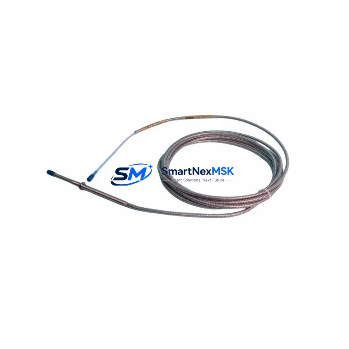
Bently Nevada 330104-09-15-10-02-00 Retrofit-Ready Proximity Transducer for 3300 XL Control Systems
The Bently Nevada 330104-09-15-10-02-00 is an 8mm proximity transducer engineered for seamless integration into legacy 3300 XL vibration monitoring systems. Whether you are replacing a discontinued sensor on an aging turbine protection panel, upgrading a control cabinet to meet current reliability standards, or restoring a critical monitoring loop after an unplanned failure, this transducer delivers verified drop-in compatibility with the 3300 XL series signal conditioning chain. Every unit is pre-shipment tested against Bently Nevada factory specifications and backed by a 12-month warranty, giving maintenance engineers and procurement teams the confidence to commit to a retrofit without extended lead times or costly re-engineering.
Upgrade Compatibility Table
| Parameter | 330104-09-15-10-02-00 (This Unit) | Notes / Retrofit Guidance |
|---|---|---|
| Sensor Diameter | 8 mm | Matches standard 3300 XL probe bore; no re-machining required |
| Cable Length | 9 m (extension + probe) | Verify existing conduit run before ordering alternate lengths |
| Connector Type | Standard BNC / coaxial | Compatible with 3300 XL proximitor input terminals |
| Proximitor Compatibility | 3300 XL Proximitor (e.g. 330180) | Confirm proximitor gap voltage range matches probe sensitivity |
| Signal Output | −18 VDC nominal at 1.0 mm gap | Calibrate gap at commissioning; target −10 to −18 VDC operating window |
| Installation Standard | API 670 compliant | Suitable for turbine, compressor, and pump shaft monitoring |
| Communication Protocol | Analog (4–20 mA / voltage) | No protocol migration required; direct replacement |
| Replacement Recommendation | Direct drop-in for 330104 series | Cross-reference OEM part number before installation |
| Commissioning Focus | Gap setting, polarity, shielding | Use Bently Nevada gap tool; verify shield grounding at one end only |
| Warranty | 12 Months | Covers manufacturing defects; includes pre-shipment functional test report |
Retrofit Planning for Existing Automation Systems
Integrating the 330104-09-15-10-02-00 into an existing plant automation architecture requires a structured review of the surrounding signal chain and control infrastructure. Begin by auditing the proximitor module — typically a Bently Nevada 330180 or equivalent 3300 XL Proximitor — to confirm that its gap voltage output range aligns with the replacement probe’s sensitivity curve. If the proximitor itself is approaching end-of-life, this retrofit is an ideal opportunity to replace it simultaneously, eliminating a second unplanned outage window.
Next, inspect the field wiring from the probe tip through the extension cable to the proximitor input terminal. The 330104-09-15-10-02-00 uses a standard coaxial signal path; verify that existing conduit and cable trays can accommodate the 9-metre cable assembly without sharp bends that could degrade signal integrity. Where cable runs have been extended with field splices, replace the full assembly to maintain impedance continuity.
At the rack level, confirm that the 3300 XL monitor card — such as the 3300/16 or 3300/20 dual-channel monitor — is configured for the correct transducer type and gap range. If the rack also houses a 3500 series monitor card as part of a phased migration, note that the 330104 probe family is forward-compatible with 3500/42M and 3500/45 position monitor modules, simplifying future platform upgrades without re-probing the machine.
For plants running a DCS backbone — such as a Honeywell Experion PKS, Emerson DeltaV, or ABB System 800xA — the 4–20 mA analog output from the 3300 XL rack feeds directly into the DCS I/O marshalling cabinet. Confirm that the AI channel scaling in the DCS controller matches the transducer’s engineering unit range (typically 0–25 mils or 0–500 µm peak-to-peak). No fieldbus or protocol migration is required for this replacement, which significantly reduces commissioning risk.
If the plant is also upgrading its HMI layer — for example, migrating from a legacy Wonderware InTouch panel to a modern SCADA platform — ensure that the vibration tag names and alarm setpoints are preserved during the HMI migration. The 330104-09-15-10-02-00 does not alter the signal chain upstream of the DCS, so existing tag structures remain valid. Similarly, if a System 1 condition monitoring software instance is connected to the 3300 XL rack via a serial or Ethernet gateway, no reconfiguration of the monitoring database is required after the probe swap.
Finally, document the as-found and as-left gap voltage readings during the retrofit. This data supports both the 12-month warranty claim process and future predictive maintenance trending. All units ship with a pre-shipment functional test report confirming output linearity and insulation resistance.
Downtime Control During System Migration
Minimising unplanned downtime is the primary concern for any maintenance team executing a proximity transducer replacement on a running production line. The 330104-09-15-10-02-00 is designed to support a hot-swap procedure where plant operating procedures and safety systems permit: the replacement probe can be pre-gapped on a bench fixture, pre-wired to the extension cable, and staged at the machine before the planned outage window opens.
During the outage, follow a structured sequence: isolate the 3300 XL monitor channel (place the channel in bypass mode to suppress spurious trips), remove the existing probe and extension cable assembly, install the 330104-09-15-10-02-00, and restore the gap to the OEM-specified value using a calibrated gap tool. Re-enable the monitor channel and verify the gap voltage reading at the proximitor output terminal before releasing the machine to operations.
To protect existing program logic, confirm that the PLC or DCS controller — whether a Rockwell Automation ControlLogix, Siemens S7-400, or equivalent platform — has the vibration interlock logic placed in manual override during the swap window. This prevents a nuisance trip from the open-circuit condition that exists momentarily during probe removal. Restore automatic mode only after the gap voltage has stabilised within the normal operating band.
For systems where continuous monitoring is contractually required (e.g., API 670 mandatory protection systems), a temporary portable vibration analyser can be connected to the proximitor output during the swap to maintain surveillance. This approach keeps the protection function active throughout the maintenance window and satisfies most insurance and regulatory audit requirements. With pre-staged hardware and a disciplined procedure, total outage time for a single-channel probe replacement is typically under 90 minutes.
Retrofit Support FAQ
Q1: Is the 330104-09-15-10-02-00 a direct replacement for all 330104 series variants?
The 330104-09-15-10-02-00 is a direct replacement for other 330104 series configurations sharing the same 8 mm probe diameter and 3300 XL proximitor compatibility. Variants differ primarily in cable length and connector termination. Always cross-reference the full part number — including the cable length suffix — against your existing installation drawing before ordering. If your existing probe is a different cable length variant (e.g., 330104-09-30-10-02-00), the probe tip and proximitor remain compatible, but the extension cable assembly must be adjusted to match the field run.
Q2: What commissioning checks are required after installation?
After mechanical installation, measure the gap voltage at the proximitor output with the shaft stationary. The target gap voltage for the 3300 XL system is typically −10 to −18 VDC; consult the machine OEM’s vibration probe specification sheet for the exact setpoint. Verify that the shield drain wire is grounded at the proximitor end only. Confirm that the monitor channel alarm and danger setpoints are active and that the System 1 or equivalent condition monitoring software is receiving a valid signal before returning the machine to service.
Q3: How is wiring compatibility verified before installation?
Compare the terminal block wiring diagram on the existing 3300 XL proximitor against the replacement probe’s connector pinout. The 330104-09-15-10-02-00 uses a standard coaxial signal conductor with a drain shield — no rewiring of the proximitor input terminal is required for a like-for-like replacement. If the existing field cable has been extended with a non-OEM splice, replace the full cable assembly to ensure impedance continuity and eliminate a potential noise source.
Q4: What does the 12-month warranty cover, and what documentation is provided?
The 12-month warranty covers manufacturing defects in materials and workmanship from the date of shipment. Each unit ships with a pre-shipment functional test report documenting gap voltage linearity, insulation resistance, and connector integrity. Warranty claims require the test report and proof of purchase. The warranty does not cover damage resulting from incorrect gap setting, mechanical impact, or installation in an incompatible proximitor system. Contact our technical support team before installation if you have any compatibility questions.
© 2026 SMARTNEXMSK. All rights reserved.
Original Source: https://smartnexmsk.com
Contact: sales@smartnexmsk.com | +86 18259474341


