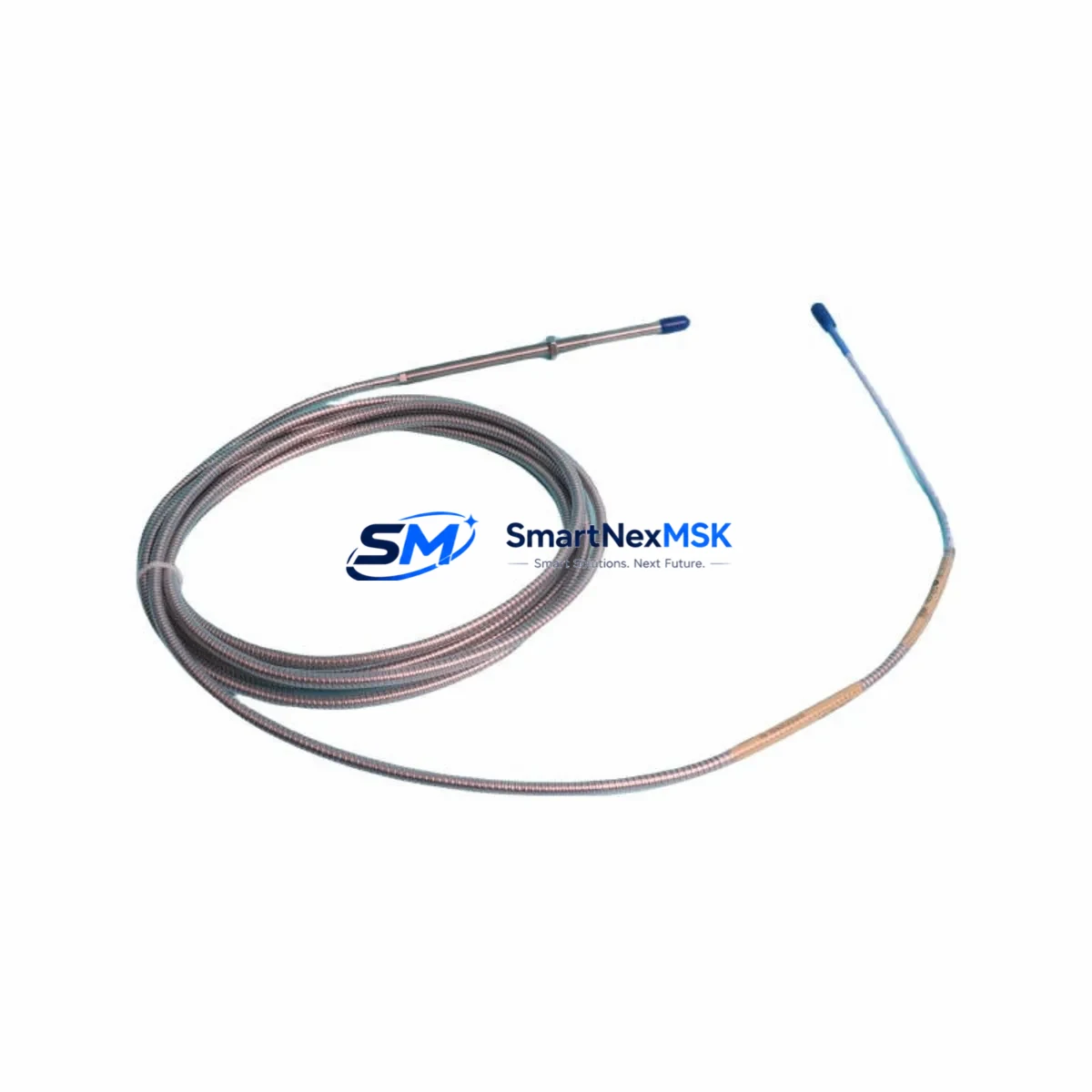
Bently Nevada 330104-09-19-10-02-00 Spare for 3300 XL Automation
The Bently Nevada 330104-09-19-10-02-00 is an original eddy current proximity transducer engineered for the 3300 XL Series continuous machinery monitoring system. Designed for critical rotating equipment applications — including turbines, compressors, pumps, and gearboxes — this transducer delivers precise non-contact displacement and vibration measurement essential for predictive maintenance programs and unplanned downtime prevention. Sourced from verified supply channels, each unit is inspection-tested prior to dispatch and backed by a 12-month warranty, ensuring maintenance engineers and procurement teams can act with confidence when replacing aging or failed sensors in live production environments.
Whether you are executing a planned outage, responding to a vibration alarm, or building a critical-spares inventory for a rotating machinery train, the 330104-09-19-10-02-00 is a direct-fit replacement that preserves system calibration integrity and minimizes re-commissioning time on the 3300 XL monitor rack.
Spare Maintenance Table
| Parameter | Specification |
|---|---|
| Part Number / SKU | 330104-09-19-10-02-00 |
| Brand | Bently Nevada |
| Series | 3300 XL |
| Product Type | Eddy Current Proximity Transducer |
| Probe Length | 9 mm tip diameter, 19 mm body length (per SKU suffix) |
| Cable Length | 10 ft (approx. 3 m) integral cable |
| Connector Type | 2-pin MIL-spec connector, compatible with 3300 XL extension cables |
| Measurement Range | 0–90 mil (0–2.25 mm) linear range |
| Output Sensitivity | 200 mV/mil (7.87 V/mm) nominal |
| Supply Voltage | −24 VDC (via Proximitor/Seismic Monitor) |
| Operating Temperature | −35°C to +177°C (probe tip) |
| Target Material Compatibility | AISI 4140 steel (standard); verify for non-ferrous shafts |
| Compatible Monitor | Bently Nevada 3300 XL Series (3300/16, 3300/20, 3300/25, 3300/55) |
| Compatible Proximitor | 330180 Series Proximitor Sensor |
| Installation | Threaded mount; torque to manufacturer specification |
| Application Environment | Turbines, compressors, pumps, gearboxes, fans — Class I Div 2 rated |
| Condition | Original / New — pre-shipment tested |
| Warranty | 12 Months |
| Lead Time | In stock — ships within 1–3 business days |
Maintenance Planning for Continuous Operation
When replacing the 330104-09-19-10-02-00 proximity transducer during a scheduled or emergency outage, a disciplined maintenance engineer will treat the transducer swap as an opportunity to inspect the entire vibration monitoring loop and adjacent control-cabinet components. Failure to audit surrounding hardware is a leading cause of repeat alarms and premature sensor failure after reinstallation.
Begin with the 330180 Series Proximitor Sensor — the signal conditioning module that pairs directly with this transducer. A degraded Proximitor will produce erratic gap voltage readings even with a new probe installed, masking the true source of the fault. Verify the Proximitor output voltage sits within the −10 to −18 VDC window at the nominal air gap before closing the cabinet.
Next, inspect the 3300 XL extension cable (typically 330130 or 330140 series, matched to total system cable length). Extension cables routed through cable trays near high-voltage bus bars are susceptible to insulation breakdown and shield continuity loss, both of which introduce noise into the 200 mV/mil signal chain. Replace any cable showing cracked jacket, corroded connectors, or measured shield resistance above specification.
The 3300/16 or 3300/20 monitor module in the rack should be checked for alarm setpoint integrity and OK relay status. If the monitor has been in service for more than five years without a firmware update or relay test, schedule a bench calibration cycle during the same outage window. Confirm that the 3300 XL power supply module — typically a dedicated −24 VDC rail — is delivering stable voltage under load; a sagging supply rail is a common root cause of intermittent OK dropouts that are incorrectly attributed to transducer failure.
For machines with dual-probe radial vibration measurement (X–Y configuration), always replace both the X-axis and Y-axis transducers as a matched pair when one fails, and cross-check the 330104-09-19-10-02-00 gap voltage against its paired probe to confirm shaft centerline position is within the acceptable window before restart.
In the wider control cabinet, inspect terminal blocks and DIN-rail mounted signal isolators serving the vibration channels. Loose terminations on the monitor’s rear I/O connector are a frequent source of intermittent faults that survive initial post-maintenance testing but reappear under thermal cycling. If the machine interfaces with a DCS or safety system via a 4–20 mA output card from the 3300 XL rack, verify the analog output scaling and confirm the receiving DCS input card — such as a Yokogawa or Emerson I/O module — is reading correctly after the transducer replacement.
For facilities running legacy 3300 Series (non-XL) monitors alongside newer 3300 XL racks, note that the 330104-09-19-10-02-00 is XL-series specific. Confirm monitor compatibility before installation to avoid system OK relay conflicts. Maintaining a minimum of two spare transducers per critical machine train — alongside one spare Proximitor and one spare extension cable set — is the recommended inventory posture for facilities with no on-site repair capability.
Site Replacement Workflow
Step 1 — Pre-replacement verification: Confirm the replacement SKU (330104-09-19-10-02-00) matches the installed probe body length, cable length, and connector type by cross-referencing the machine’s vibration monitoring datasheet or the existing Bently Nevada system drawing. Mismatched cable lengths alter total system sensitivity and require Proximitor re-gapping.
Step 2 — Safe isolation: De-energize the monitor channel at the 3300 XL rack using the channel inhibit function (do not remove rack power) to suppress spurious alarms during probe removal. Log the pre-removal gap voltage for comparison after installation.
Step 3 — Physical replacement: Remove the old transducer using the correct spanner, noting the installed gap (number of turns from contact). Install the 330104-09-19-10-02-00 to the same gap as a starting point, then fine-adjust to achieve the target gap voltage (typically −10 to −12 VDC for mid-range positioning on AISI 4140 shafts).
Step 4 — Loop verification: Re-enable the monitor channel and confirm OK LED status, gap voltage, and vibration reading against baseline. Compare X and Y channel readings if dual-probe configuration. Document the as-left gap voltage in the maintenance record.
Step 5 — System handback: Notify the control room of channel restoration, confirm DCS analog input is tracking correctly, and update the spare parts inventory log to trigger reorder of the consumed transducer.
This workflow reduces mean time to repair (MTTR) for vibration monitoring faults from several hours to under 60 minutes when a pre-tested spare is available on-site.
Spare Parts Support FAQ
Q1: Is the 330104-09-19-10-02-00 compatible with both 3300 and 3300 XL monitors?
The 330104-09-19-10-02-00 is designed and calibrated for the 3300 XL Series. While the physical connector may fit older 3300 Series Proximitors, system sensitivity and OK relay thresholds differ between generations. Always verify monitor compatibility using the Bently Nevada system compatibility matrix before installation in a non-XL rack.
Q2: How is each unit tested before shipment?
Every 330104-09-19-10-02-00 unit undergoes pre-shipment electrical continuity, insulation resistance, and gap voltage output verification. Units that do not meet OEM output sensitivity specifications (200 mV/mil ±1%) are quarantined and not dispatched. A test report is available upon request for critical-service applications.
Q3: What is the recommended spare inventory quantity for a critical rotating machine?
For machines classified as critical (no installed spare, process-critical duty), the recommended minimum is two transducers per measurement plane, one matched Proximitor, and one extension cable set. For semi-critical machines with an installed spare rotor, one transducer per plane is typically sufficient. Review your site’s spare parts criticality matrix annually and replenish consumed spares within 30 days of use.
Q4: What does the 12-month warranty cover?
The 12-month warranty covers manufacturing defects, electrical failure under normal operating conditions, and out-of-specification output sensitivity at time of installation. It does not cover damage resulting from incorrect installation gap, mechanical impact, chemical exposure, or operation outside the rated temperature range. Warranty claims are processed with photographic evidence and the original order reference. Contact sales@smartnexmsk.com to initiate a warranty claim.
© 2026 SMARTNEXMSK. All rights reserved.
Original Source: https://smartnexmsk.com
Contact: sales@smartnexmsk.com | +86 18259474341


