Bently Nevada 330104-09-20-50-02-00 3300 XL Proximity Transducer: Retrofit-Ready Replacement for Legacy Vibration Monitoring Systems
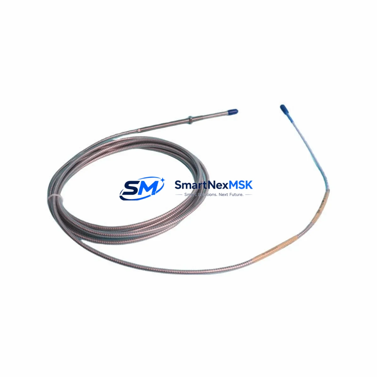
The Bently Nevada 330104-09-20-50-02-00 is a precision eddy-current proximity transducer engineered for the 3300 XL Series monitoring platform. Designed with an 8 mm tip diameter, 5-metre armored cable, and a –24 VDC bias voltage output, this unit delivers direct drop-in compatibility for facilities retiring aging 3300 Series transducers or upgrading from earlier Bently Nevada 7200 Series installations. Whether your plant is executing a full control-system modernization or replacing a single failed sensor on a critical rotating machine, the 330104-09-20-50-02-00 provides the dimensional accuracy, signal linearity, and environmental robustness demanded by turbine, compressor, and pump monitoring applications.
Industrial sites operating legacy machinery face a recurring challenge: original-equipment transducers reach end-of-life while the rotating assets they protect continue to run. Sourcing a verified replacement that maintains calibration traceability, preserves existing wiring infrastructure, and integrates without reprogramming the 3300 XL monitor rack is essential to controlling both downtime and capital expenditure. The 330104-09-20-50-02-00 addresses each of these requirements directly, making it the preferred retrofit choice for maintenance engineers and reliability teams worldwide.
Upgrade Compatibility Table
| Parameter | Detail |
|---|---|
| SKU / Part Number | 330104-09-20-50-02-00 |
| Series Compatibility | Bently Nevada 3300 XL Series; backward-compatible with 3300 Series monitor racks |
| Tip Diameter | 8 mm (standard eddy-current probe) |
| Cable Length | 5 m (armored, integral) |
| Output Bias Voltage | –24 VDC nominal |
| Supply Voltage | –24 VDC (from 3300 XL proximitor / driver) |
| Connector Interface | Standard BNC / coaxial to proximitor driver (330180 or 330130 series) |
| Installation Requirement | Threaded mounting boss; gap set to 1.0–1.5 mm per OEM specification |
| Common Replacement For | 330104-09-20-50-02-00, 330104-09-20-50-00-00, 7200-series 8 mm probes |
| Communication / Signal | Analog voltage output; compatible with 3300 XL monitor I/O cards and 1900/65 series monitors |
| Commissioning Note | Verify gap voltage at proximitor output; recalibrate alert/danger setpoints in monitor rack after installation |
| Warranty | 12-Month Warranty — covers manufacturing defects and signal performance |
Retrofit Planning for Existing Automation Systems
A successful retrofit begins well before the transducer is unboxed. Maintenance teams should first audit the existing 3300 XL monitor rack to confirm which I/O slots are occupied by proximity input cards and whether the associated proximitor driver — typically a 330180-X1-05 or 330130-040-01-00 — is still within its calibration interval. The driver and transducer form a matched system; replacing only the probe while retaining a degraded driver will introduce measurement error that no amount of setpoint adjustment can correct.
Terminal wiring for the 330104-09-20-50-02-00 follows the standard three-conductor arrangement: power (–24 VDC), signal (output), and common (shield/ground). Before disconnecting the old probe, photograph or document the existing terminal block layout on the monitor rack’s I/O card. Many 3300 XL racks use a 3300/16-channel I/O module with clearly labeled terminals; however, older installations may have field-wired junction boxes where shield continuity is critical to noise rejection. Confirm that the cable shield is grounded at one end only — typically at the monitor rack — to prevent ground loops that manifest as elevated noise floors on the vibration channel.
For plants running a Bently Nevada System 1 condition-monitoring software platform, the transducer replacement should be logged as a configuration change event. Update the transducer serial number, installation date, and gap voltage reading in the System 1 database to maintain audit traceability. If the facility also operates a 3500 Series rack alongside the 3300 XL, note that the 3500/42M proximity monitor card uses a different I/O module pinout and is not directly interchangeable with 3300 XL rack wiring — plan accordingly if a phased migration to the 3500 platform is on the roadmap.
Sites upgrading from legacy 7200 Series 8 mm probes will find the 330104-09-20-50-02-00 dimensionally compatible in most mounting bosses, but should verify thread pitch (M10 × 1.0 is standard) and confirm that the replacement proximitor driver is a 330180 rather than the older 7200-series driver, as the scale factor differs (7.87 V/mm for 3300 XL versus 7.87 V/mm nominal for 7200, but with different temperature compensation curves). A brief bench calibration using a calibration fixture and a 3300 XL proximitor before field installation eliminates ambiguity.
When the control cabinet also houses a Bently Nevada 3300/20-04 power supply module, inspect its output voltage under load before commissioning the new transducer. A sagging supply rail — common in cabinets with aging capacitors — will shift the transducer’s linear range and produce false proximity readings. Replacing the power supply module proactively during the same maintenance window avoids a repeat outage. Similarly, if the rack includes a 3300 XL keyphasor module (330180-X1-05 driver paired with a once-per-revolution target), verify that the keyphasor gap and signal are within specification, as the vibration channels reference the keyphasor for phase and 1× amplitude calculations.
Downtime Control During System Migration
Minimizing production interruption during a transducer swap requires a structured sequence. Begin by placing the affected monitor channel in bypass mode within the 3300 XL rack — this suppresses the danger relay output for that channel without affecting adjacent channels or the overall machine protection logic. Document the current alert and danger setpoints, gap voltage, and any active alarms before powering down the field wiring.
With the channel bypassed, disconnect the coaxial cable at the proximitor driver, remove the old 330104-series probe from its mounting boss, and install the replacement 330104-09-20-50-02-00. Set the air gap to the OEM-specified range (typically 1.0–1.5 mm, yielding a gap voltage of approximately –10 to –11 VDC at the proximitor output). Reconnect the coaxial cable, restore power to the driver, and verify the gap voltage reading on the monitor rack’s front-panel display or via System 1 software before removing the channel bypass.
For facilities where the machine cannot be taken offline, a hot-swap approach is possible if a spare monitor channel is available in the rack: wire the new transducer to the spare channel, verify its output, then switch the protection logic to the new channel before removing the old probe. This technique keeps machine protection active throughout the swap and is particularly valuable on critical compressors or turbines where any unmonitored period represents unacceptable risk. Once the new channel is confirmed stable, the old channel can be decommissioned and the rack configuration updated in System 1.
All replacement units shipped by SMARTNEXMSK undergo pre-shipment functional testing — gap voltage linearity, cable continuity, and connector integrity are verified before dispatch. Each unit ships with a test report and is covered by a 12-month warranty against manufacturing defects and signal performance deviations, giving your maintenance team confidence that the replacement will perform from the first power-on.
Retrofit Support FAQ
Q1: Is the 330104-09-20-50-02-00 a direct replacement for the 330104-09-20-50-00-00?
Yes. The –02-00 suffix denotes the connector option; both variants share identical tip geometry, cable length, scale factor, and mounting thread. The replacement is electrically and mechanically interchangeable in all standard 3300 XL rack installations. Confirm the connector type at the proximitor driver end before ordering if your installation uses a non-standard junction box.
Q2: Do I need to recalibrate the monitor rack after installing the new transducer?
You do not need to recalibrate the rack’s internal electronics, but you must verify and re-set the physical air gap to achieve the correct gap voltage (–10 to –11 VDC). After gap adjustment, confirm that the alert and danger setpoints in the 3300 XL monitor card still reflect your machinery protection requirements. If the previous probe had drifted, the new probe’s accurate output may cause previously masked alarms to become active — this is expected behavior, not a fault.
Q3: What wiring checks should I perform before commissioning?
Verify shield continuity from the probe connector to the proximitor driver, confirm that the shield is grounded at the monitor rack end only, and measure the supply voltage at the driver (–24 VDC ± 1 V). Check that the coaxial cable has no sharp bends within 150 mm of the probe body, as mechanical stress at the cable entry point is the most common cause of premature failure in high-vibration environments.
Q4: What does the 12-month warranty cover, and how is it claimed?
The 12-month warranty covers manufacturing defects, signal linearity deviations outside the published specification, and cable or connector failures under normal operating conditions. It does not cover damage resulting from incorrect gap setting, reverse polarity wiring, or mechanical impact. To initiate a warranty claim, contact SMARTNEXMSK with the unit serial number, installation date, and a description of the observed fault. Replacement units are dispatched within 3 business days of claim approval.
© 2026 SMARTNEXMSK. All rights reserved.
Original Source: https://smartnexmsk.com
Contact: sales@smartnexmsk.com | +86 18259474341


