Bently Nevada 330104-10-13-05-02-CN Retrofit-Ready Proximity Transducer for 3300 XL Control Systems
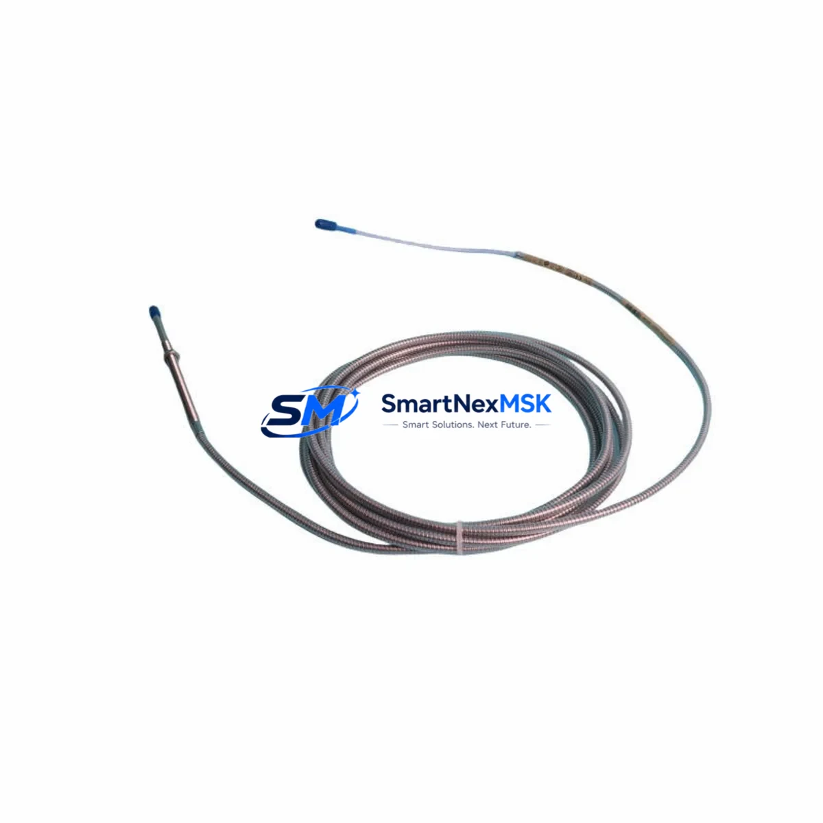
The Bently Nevada 330104-10-13-05-02-CN is an 8mm eddy-current proximity transducer engineered for seamless drop-in replacement and retrofit integration within Bently Nevada 3300 XL vibration monitoring systems. Designed to meet the demanding requirements of industrial turbomachinery protection, this unit delivers reliable shaft displacement and vibration measurement in legacy and modernized control architectures alike. Whether you are replacing a failed sensor on a running production line, upgrading an aging 3300 Series rack to the 3300 XL platform, or restoring a mothballed asset, this transducer provides the electrical and mechanical compatibility needed to minimize engineering rework and reduce commissioning time.
The 330104-10-13-05-02-CN ships with a 5-meter extension cable and a CN-type driver, maintaining full signal chain compatibility with existing 3300 XL monitor cards such as the 3300/16 and 3300/20 series. The probe tip geometry and thread specification match the original Bently Nevada factory standard, allowing direct installation into existing probe holders and armored conduit runs without modification. Power supply requirements align with standard ±24 VDC instrument rails commonly found in turbine control cabinets, eliminating the need for auxiliary power conditioning during retrofit.
Upgrade Compatibility Table
| Parameter | 330104-10-13-05-02-CN | Notes |
|---|---|---|
| Probe Diameter | 8 mm | Direct fit to standard 3300 XL probe holders |
| Cable Length | 5 m (extension) | Compatible with existing conduit runs |
| Driver Type | CN (3300 XL) | Matches 3300/16, 3300/20 monitor card inputs |
| Supply Voltage | ±24 VDC | Standard instrument rail; no converter required |
| Output Signal | -18 VDC nominal | Calibrated per Bently Nevada factory spec |
| Thread Specification | M10 × 1.0 | No probe holder modification needed |
| Communication Protocol | Analog (4–20 mA / voltage) | Compatible with legacy DCS and safety system inputs |
| Replacement Compatibility | 3300 Series, 3300 XL Series | Verified cross-reference to original Bently Nevada BOM |
| Installation Requirement | Gap voltage calibration required | Target: -10.0 VDC ± 0.5 VDC at nominal gap |
| Commissioning Check | Static and dynamic signal verification | Confirm with 3300 XL rack front-panel indicators |
| Warranty | 12 Months | Covers manufacturing defects; full replacement policy |
Retrofit Planning for Existing Automation Systems
Successful retrofit of the 330104-10-13-05-02-CN into an existing turbomachinery protection system requires a structured pre-installation review. Begin by auditing the current rack configuration. Most 3300 XL installations use a standard 19-inch rack chassis housing multiple monitor cards, a power supply module, and a system rack interface. Confirm that the existing 3300 XL rack power supply — typically a Bently Nevada 3300/05 or equivalent — can support the additional transducer load without exceeding its rated output current. In multi-channel installations where several proximity probes are being replaced simultaneously, total current draw across all channels must be recalculated.
Next, inspect the existing terminal block wiring. The 330104-10-13-05-02-CN uses a standard three-conductor connection: power, common, and signal output. Verify that the existing field wiring terminations at the 3300 XL monitor card input terminals are correctly labeled and that no conductor insulation has degraded over the service life of the original probe. In older installations, it is common to find that terminal screws have loosened due to thermal cycling; re-torque all connections to specification before powering the new transducer.
For sites migrating from the earlier Bently Nevada 3300 Series (non-XL) to the 3300 XL platform, the backplane interface and rack address configuration must be reviewed. The 3300 XL monitor cards use a different slot addressing scheme than the legacy 3300 Series, and program logic in the associated safety system or DCS — such as a Honeywell TDC 3000, Emerson DeltaV, or ABB 800xA — may reference channel-specific tag names tied to the old rack slot assignments. Update all PLC or DCS tag mappings before commissioning the new transducer to prevent false alarms or missed trips.
HMI screen configurations should also be reviewed. Operator displays that show vibration trend data, alarm setpoints, and trip thresholds are typically linked to specific I/O tags. If the retrofit involves a rack slot change or a channel reassignment, the HMI graphics — whether running on a GE Cimplicity, Wonderware InTouch, or Siemens WinCC platform — must be updated to reflect the new tag structure. Failure to update HMI bindings is one of the most common causes of post-retrofit alarm nuisance trips.
Communication link integrity between the 3300 XL rack and the plant DCS or safety instrumented system (SIS) should be verified using the existing Modbus RTU or Modbus TCP/IP link, depending on the site communication architecture. Some older installations use a dedicated Bently Nevada Data Manager or System 1 software interface for vibration data trending; confirm that the new transducer’s output signal is correctly recognized by the System 1 configuration database before returning the machine to service.
For I/O expansion projects where additional measurement points are being added alongside the transducer replacement, consider whether the existing 3300 XL rack has available monitor card slots. If the rack is fully populated, a secondary rack with its own power supply and backplane may be required. In such cases, the Bently Nevada 3300/05 rack power supply and a compatible rack interface module should be sourced alongside the 330104-10-13-05-02-CN to complete the bill of materials. Programming cables such as the Bently Nevada 3300 Series configuration cable may also be needed if monitor card parameters require adjustment during commissioning.
Downtime Control During System Migration
Minimizing unplanned downtime during a proximity transducer replacement is a primary concern for any rotating equipment reliability team. The 330104-10-13-05-02-CN is designed to support a rapid swap procedure that, when properly planned, can be completed within a single planned maintenance window without requiring a full system shutdown beyond the affected measurement channel.
Before beginning the physical replacement, export and archive the current 3300 XL monitor card configuration using the Bently Nevada configuration software. This preserves all alarm setpoints, trip thresholds, time delays, and channel-specific calibration offsets. If the monitor card must be removed from the rack during the probe replacement, having a saved configuration file allows the card to be restored to its exact pre-outage state within minutes, rather than requiring a full manual re-entry of all parameters.
During the physical swap, maintain the existing field wiring connections at the terminal block as long as possible. Disconnect only the probe and extension cable at the field junction box, leaving the monitor card input terminals undisturbed. This approach preserves the wiring integrity and reduces the risk of introducing wiring errors during reconnection. Once the new 330104-10-13-05-02-CN is installed and the gap voltage has been set to the target value of -10.0 VDC ± 0.5 VDC using a calibrated digital multimeter, reconnect the extension cable and verify the signal at the monitor card input before re-enabling the channel.
For critical machines where continuous monitoring is required, consider using a temporary bypass or inhibit function available on most 3300 XL monitor cards to suppress the affected channel alarm during the swap interval. Document the inhibit start and end times in the plant maintenance management system and notify the control room operator before and after the bypass is applied. This procedure maintains plant safety awareness while allowing the physical replacement to proceed without generating nuisance alarms or spurious trips on the safety system.
After the replacement is complete and the channel has been re-enabled, allow the machine to run for a minimum of 30 minutes under normal operating conditions before confirming the retrofit as complete. Compare the new transducer’s vibration trend data against the historical baseline stored in the System 1 or equivalent condition monitoring platform to confirm that the signal quality and amplitude are consistent with pre-replacement readings. Any significant deviation should be investigated before closing the work order.
Retrofit Support FAQ
Q1: Is the 330104-10-13-05-02-CN a direct replacement for the original Bently Nevada part, or are there wiring or configuration differences I need to account for?
A: The 330104-10-13-05-02-CN is a verified drop-in replacement for the original Bently Nevada factory part of the same SKU. The probe thread, cable connector, driver type, and output signal characteristics are manufactured to the original specification. No wiring changes are required at the monitor card terminal block. The only field adjustment needed is the standard gap voltage calibration to -10.0 VDC ± 0.5 VDC, which is required for any new proximity probe installation regardless of brand or source.
Q2: What commissioning steps are required after installation, and how do I verify the transducer is functioning correctly?
A: After physical installation and gap voltage calibration, verify the static output signal at the 3300 XL monitor card input using the front-panel LED indicators or the Bently Nevada configuration software. Confirm that the channel is reading within the normal vibration range for the machine at rest (typically below 25 µm pk-pk for well-balanced rotating equipment). Apply a dynamic check by briefly touching the probe tip with a non-ferrous tool to confirm the monitor card responds to a simulated vibration input. Log the as-found and as-left gap voltage readings in the plant maintenance record before returning the channel to service.
Q3: Does the 12-month warranty cover field failures caused by installation errors or environmental exposure?
A: The 12-month warranty covers manufacturing defects in materials and workmanship under normal operating conditions. It does not cover damage resulting from incorrect installation, overvoltage conditions, mechanical impact, or exposure to fluids or chemicals beyond the probe’s rated environmental specification. To protect your warranty claim, retain the original packaging, document the installation gap voltage reading, and ensure the probe is installed in a location that meets the Bently Nevada environmental rating for the 330104 series. If a warranty claim is required, contact sales@smartnexmsk.com with the order reference and a description of the failure mode.
Q4: Can this transducer be used with third-party vibration monitoring systems, or is it limited to Bently Nevada 3300 XL racks?
A: The 330104-10-13-05-02-CN is optimized for use with Bently Nevada 3300 XL monitor cards and is calibrated to the Bently Nevada driver sensitivity standard of 7.87 V/mm (200 mV/mil). It can be used with third-party vibration monitoring systems that accept a standard eddy-current transducer input at this sensitivity, provided the third-party system’s input impedance and power supply voltage are compatible. Consult your third-party monitor manufacturer’s specifications before cross-application. For guaranteed compatibility and warranty coverage, use with Bently Nevada 3300 XL hardware is recommended.
© 2026 SMARTNEXMSK. All rights reserved.
Original Source: https://smartnexmsk.com
Contact: sales@smartnexmsk.com | +86 18259474341


