Bently Nevada 330104-10-20-10-02-CN Retrofit-Ready Proximity Transducer for 3300 XL Control Systems
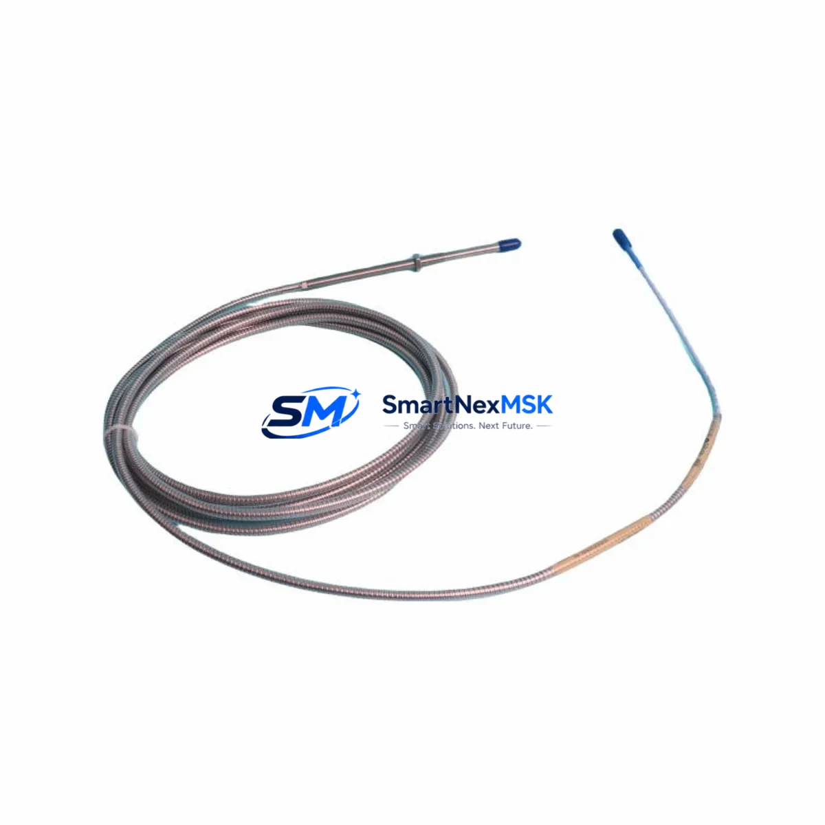
The Bently Nevada 330104-10-20-10-02-CN is an 8mm eddy current proximity transducer engineered for the 3300 XL Series machinery protection system. As legacy rotating machinery monitoring infrastructure ages across power generation, petrochemical, and heavy industrial facilities, this transducer serves as a verified drop-in retrofit solution for plants seeking to extend the operational life of their existing 3300 XL monitoring architecture without committing to a full platform migration. Whether you are replacing a failed unit, building a critical spare inventory, or executing a planned control system upgrade, the 330104-10-20-10-02-CN delivers the dimensional accuracy, signal linearity, and environmental resilience required for continuous shaft vibration and position monitoring in demanding plant environments.
Upgrade Compatibility Table
| Parameter | Details |
|---|---|
| SKU / Part Number | 330104-10-20-10-02-CN |
| Series Compatibility | Bently Nevada 3300 XL Machinery Protection System |
| Transducer Type | 8mm Eddy Current Proximity Transducer |
| Cable Length | 1.0 m integral cable (extension cable required for full system loop) |
| Connector Type | Standard BNC / coaxial — compatible with 3300 XL extension cables and drivers |
| Driver / Proximitor Compatibility | 3300 XL 8mm Proximitor Sensor (e.g. 330180 series) |
| Installation Requirement | M10 threaded housing; verify bracket clearance and gap voltage per OEM spec |
| Communication / Signal | Analog DC voltage output; integrates with 3500 Series rack monitors via standard wiring |
| Replacement Recommendation | Direct retrofit for failed or end-of-life 330104-10-20-10-02-CN units |
| Commissioning Note | Re-gap to OEM specification (typically –10 VDC at mid-range); verify with oscilloscope or Proximitor tester |
| Warranty | 12-Month Warranty — covers manufacturing defects and functional failure under normal operating conditions |
Retrofit Planning for Existing Automation Systems
Successful integration of the 330104-10-20-10-02-CN into an existing 3300 XL or 3500 Series monitoring loop requires systematic pre-installation verification across several interdependent subsystems. Before removing the failed transducer, technicians should document the current gap voltage reading at the Proximitor output terminal and record the baseline vibration trend data from the associated 3500/22M Transient Data Interface or 3500/42M Proximitor Monitor card to preserve pre-retrofit reference values.
The extension cable — typically a Bently Nevada 330130 or 330140 series armored extension cable — must be inspected for continuity and shield integrity before reuse. A damaged extension cable is a common source of signal noise that is frequently misattributed to transducer failure. Similarly, the 330180 Series 8mm Proximitor Sensor mounted in the field junction box should be tested for correct bias voltage output before assuming the transducer is the sole failed component.
At the rack level, the 3500/20 Rack Interface Module and the associated 3500/15 Power Supply Module should be confirmed operational, as power rail instability can cause erratic proximity readings that mimic transducer degradation. If the plant is running a hybrid monitoring architecture that combines legacy 3300 XL field hardware with a newer 3500 Series rack, verify that the channel configuration in the System 1 Evolution software correctly maps the transducer type, scale factor, and OK limit thresholds for the 8mm probe family.
For facilities executing a broader control system modernization — for example, migrating from a legacy Bently Nevada 7200 Series or 3300 Series rack to the current 3500 platform — the 330104-10-20-10-02-CN provides a cost-effective field hardware continuity strategy. The transducer and its associated 330180 Proximitor can remain in service while the rack infrastructure is upgraded, eliminating the need for simultaneous field and rack replacement and significantly reducing total project downtime. During this transition, the 3500/92 Communication Gateway Module can be configured to bridge legacy Modbus RTU data streams to the plant DCS or historian, maintaining data continuity throughout the migration window.
Wiring adaptation should be verified at the field terminal block level. Confirm that the coaxial cable shield is grounded at one end only (typically at the Proximitor housing) to prevent ground loop interference. Terminal torque values, cable routing separation from high-voltage conductors, and conduit sealing at hazardous area boundaries must all be re-verified after transducer replacement to maintain SIL and area classification compliance.
Downtime Control During System Migration
Minimizing unplanned downtime during a proximity transducer retrofit begins with pre-staging. The replacement 330104-10-20-10-02-CN should be bench-tested against a known-good 330180 Proximitor before the maintenance window opens, confirming the gap voltage curve and OK relay behavior match OEM specifications. This eliminates the risk of discovering a second failed component after the machine has been taken offline.
Where plant operations permit, a hot-standby spare strategy — maintaining one pre-gapped and tested transducer assembly per critical machine train — reduces mean time to repair to under 30 minutes for a trained technician. The original program logic in the 3500 rack requires no modification for a like-for-like transducer replacement; however, if the replacement is part of a broader channel reconfiguration, the 3500 Rack Configuration Software should be used to export and archive the existing channel setup before any changes are made, protecting the original control logic and alarm setpoints.
HMI screens connected to the machinery protection system — whether running on a dedicated Bently Nevada operator workstation or integrated into a plant-wide SCADA via OPC-DA or OPC-UA — should be monitored throughout the commissioning process to confirm that the new transducer’s signal is correctly received and that no spurious OK-relay trips are generated during the gap adjustment procedure. Field commissioning should be completed with the machine at rest before returning to normal operating speed, with a final vibration trend comparison against the pre-retrofit baseline to confirm signal fidelity.
Retrofit Support FAQ
Q: Is the 330104-10-20-10-02-CN a direct replacement for my existing 3300 XL 8mm transducer?
A: Yes. The 330104-10-20-10-02-CN is dimensionally and electrically compatible with the 3300 XL 8mm proximity transducer family. It is designed for direct installation into existing M10 threaded mounting brackets without mechanical modification. Re-gapping to OEM specification is required after installation.
Q: What commissioning steps are required after installation?
A: After mechanical installation, adjust the transducer gap to achieve the OEM-specified bias voltage (typically –10 VDC ±0.5 VDC at mid-range) using a calibrated DC voltmeter at the Proximitor output terminals. Verify the OK relay status at the 3500 rack monitor card and confirm the vibration channel reads within expected baseline range before returning the machine to service.
Q: Can this transducer be used with the 3500 Series rack as well as the 3300 XL?
A: Yes. The 330104-10-20-10-02-CN is compatible with both the 3300 XL and 3500 Series monitoring platforms when paired with the appropriate 330180 Series 8mm Proximitor Sensor. Confirm channel configuration in the 3500 Rack Configuration Software to ensure the correct probe type and scale factor are selected.
Q: What does the 12-month warranty cover?
A: The 12-month warranty covers manufacturing defects and functional failure under normal operating conditions from the date of shipment. Each unit undergoes pre-shipment functional testing. Warranty claims are supported by our technical team at sales@smartnexmsk.com.
© 2026 SMARTNEXMSK. All rights reserved.
Original Source: https://smartnexmsk.com
Contact: sales@smartnexmsk.com | +86 18259474341


