Bently Nevada 330104-11-15-10-02-00 Spare for 3300 XL Automation: Precision Replacement for Continuous Machinery Monitoring
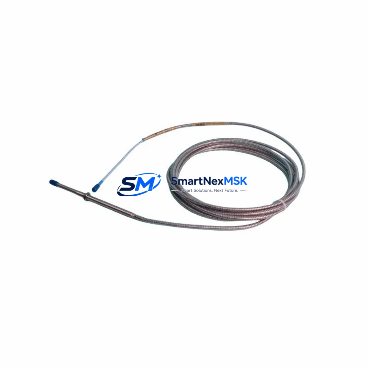
The Bently Nevada 330104-11-15-10-02-00 is an original eddy current proximity transducer engineered for the 3300 XL series continuous machinery monitoring system. Designed to measure radial shaft vibration, axial position, and differential expansion in rotating machinery, this transducer is a critical component in turbine protection, compressor monitoring, and pump condition assessment across oil & gas, power generation, petrochemical, and heavy industrial facilities. When this transducer fails or degrades, the entire vibration monitoring loop is compromised — making rapid, verified spare parts availability essential to minimizing unplanned downtime and protecting rotating assets.
Maintenance engineers and reliability teams managing aging 3300 XL installations depend on exact-match replacements to preserve system calibration, avoid re-ranging procedures, and maintain API 670 compliance. The 330104-11-15-10-02-00 features a 5 mm sensing range, 8 mm probe diameter, and operates with the standard Bently Nevada -24 VDC proximitor/driver supply. Its 100 mV/mil (3.937 V/mm) output sensitivity is factory-calibrated and verified prior to shipment, ensuring drop-in compatibility with existing 3300 XL monitor cards and field wiring without system reconfiguration.
Spare Maintenance Table
| Parameter | Specification |
|---|---|
| Part Number / SKU | 330104-11-15-10-02-00 |
| Brand | Bently Nevada |
| Series | 3300 XL |
| Product Type | Eddy Current Proximity Transducer |
| Sensing Range | 5 mm (0–200 mil) |
| Probe Diameter | 8 mm |
| Output Sensitivity | 100 mV/mil (3.937 V/mm) |
| Supply Voltage | -24 VDC (via 3300 XL Proximitor/Driver) |
| Cable Length | 15 ft (4.57 m) integral cable |
| Extension Cable | 10 ft (3.05 m) — matched system |
| Temperature Range | -35°C to +177°C (probe tip) |
| Ingress Protection | IP67 (probe body) |
| Compatibility | 3300 XL Monitor Cards, 3300/16 Rack, 3500 Series (with adapter) |
| Application | Radial vibration, axial position, differential expansion |
| Compliance | API 670, CE |
| Origin | USA |
| Warranty | 12 Months from shipment date |
| Pre-shipment Test | Output linearity, sensitivity, and insulation verified |
| Condition | Original, new or recertified — confirmed before dispatch |
Maintenance Planning for Continuous Operation
When replacing the 330104-11-15-10-02-00 in a 3300 XL monitoring loop, a thorough site inspection of the entire measurement chain is essential to prevent repeat failures and ensure signal integrity. Maintenance engineers should begin by inspecting the matched extension cable — typically the 330130-080-00-00 or equivalent 3300 XL series extension cable — for jacket abrasion, connector corrosion, and continuity. A damaged extension cable is a leading cause of transducer output drift and false vibration alarms.
The 3300 XL Proximitor/Driver (e.g., 330180-X1-05) should be tested for correct -24 VDC output and verified against its gap voltage specification. A failing proximitor will produce erratic output even with a new probe installed. Simultaneously, inspect the 3300/16 monitor rack and its associated I/O terminal blocks for loose wiring, oxidized contacts, and correct channel assignment. Relay output modules within the rack — such as the 3300/32 relay module — should be exercised and verified for correct trip setpoint response.
For installations where the 3300 XL system interfaces with a DCS or safety PLC, verify the 4–20 mA or voltage output signal at the marshalling cabinet terminal strips and confirm correct scaling at the DCS analog input card. Signal isolators or barriers — such as a Pepperl+Fuchs KFD2-STV4-Ex1 signal conditioner or equivalent — installed in the loop should be inspected for drift and replaced on a scheduled basis. Fuse holders and fuses protecting the -24 VDC proximitor supply rail should be checked and replaced if discolored or showing elevated resistance.
In control cabinets housing the 3300 XL rack, inspect the 24 VDC power supply module for output ripple and load regulation. Aging power supplies are a common root cause of system-wide vibration monitor instability. If the facility operates a Bently Nevada 3500 series rack alongside legacy 3300 XL hardware, confirm that any shared relay or communication wiring is correctly segregated and that the 3500/22M transient data interface or 3500/92 communication gateway is functioning correctly for data historian integration.
For facilities planning a phased migration from 3300 XL to 3500 series, stocking the 330104-11-15-10-02-00 as a bridge spare — alongside the 3500/42M proximitor I/O module — allows maintenance teams to sustain legacy monitoring loops while new rack infrastructure is commissioned. This dual-inventory strategy reduces emergency procurement risk and supports planned outage scheduling.
Site Replacement Workflow
Step 1 — Isolation & Permit: Obtain a hot-work or cold-work permit as applicable. Isolate the monitoring channel at the 3300 XL rack and confirm the relay output is in bypass or inhibit mode to prevent spurious trips during replacement.
Step 2 — Gap Measurement: Before removing the old transducer, record the existing gap voltage (typically -10 VDC ±0.5 V for a 50 mil gap). This baseline confirms the replacement probe is installed at the correct air gap and eliminates the need for full re-calibration if the target material and shaft surface condition are unchanged.
Step 3 — Probe Removal & Inspection: Remove the 330104-11-15-10-02-00 probe from its mounting bracket. Inspect the probe tip for impact damage, shaft rub marks, or contamination. Inspect the mounting threads and bracket for wear. Clean the target area on the shaft and verify surface finish is within specification (typically Ra ≤ 0.8 µm).
Step 4 — New Probe Installation: Install the replacement 330104-11-15-10-02-00 and set the air gap to the manufacturer-specified value using a non-ferrous feeler gauge or gap voltage measurement. Torque the locknut to specification. Reconnect the extension cable and verify connector seating.
Step 5 — Loop Verification: Power the proximitor and confirm gap voltage is within the linear range. Verify the monitor card displays correct static gap and that vibration readings are within expected baseline. Remove the bypass/inhibit and confirm relay outputs are restored to normal state.
Step 6 — Documentation: Record the replacement in the CMMS, update the spare parts inventory, and log the gap voltage and sensitivity verification results. Schedule the next inspection interval per the facility’s predictive maintenance program.
Spare Parts Support FAQ
Q1: Is the 330104-11-15-10-02-00 compatible with both 3300 XL and 3500 series monitor racks?
The 330104-11-15-10-02-00 is natively designed for the 3300 XL series. It can be used with 3500 series racks equipped with the appropriate 3500/42M proximitor I/O module, provided the cable system (probe + extension cable + proximitor) is matched as a calibrated set. Always verify the complete cable system part number before cross-series installation.
Q2: What is included in the 12-month warranty and pre-shipment testing?
Every 330104-11-15-10-02-00 unit is tested for output linearity across the full sensing range, sensitivity verification at 100 mV/mil, and insulation resistance before dispatch. The 12-month warranty covers manufacturing defects and performance deviations from published specifications under normal operating conditions, from the date of shipment.
Q3: How should I manage spare inventory for aging 3300 XL installations?
For facilities with 4 or more 3300 XL monitoring channels, we recommend maintaining a minimum of 2 matched probe-and-extension-cable sets as on-site critical spares. Given the discontinuation risk for legacy 3300 XL components, procuring a 12–24 month forward stock is a prudent strategy to avoid emergency lead times during unplanned outages.
Q4: Can I replace only the probe without replacing the extension cable and proximitor?
Yes, provided the existing extension cable and proximitor are within specification and the cable system is a matched set. However, if the extension cable shows any jacket damage, connector wear, or the proximitor output is outside tolerance, replacing the full matched set is strongly recommended to ensure system accuracy and avoid repeat failures within the same maintenance cycle.
© 2026 SMARTNEXMSK. All rights reserved.
Original Source: https://smartnexmsk.com
Contact: sales@smartnexmsk.com | +86 18259474341


