Bently Nevada 330104-11-22-10-02-CN: Retrofit-Ready 3300 XL Proximity Transducer for Legacy System Upgrades
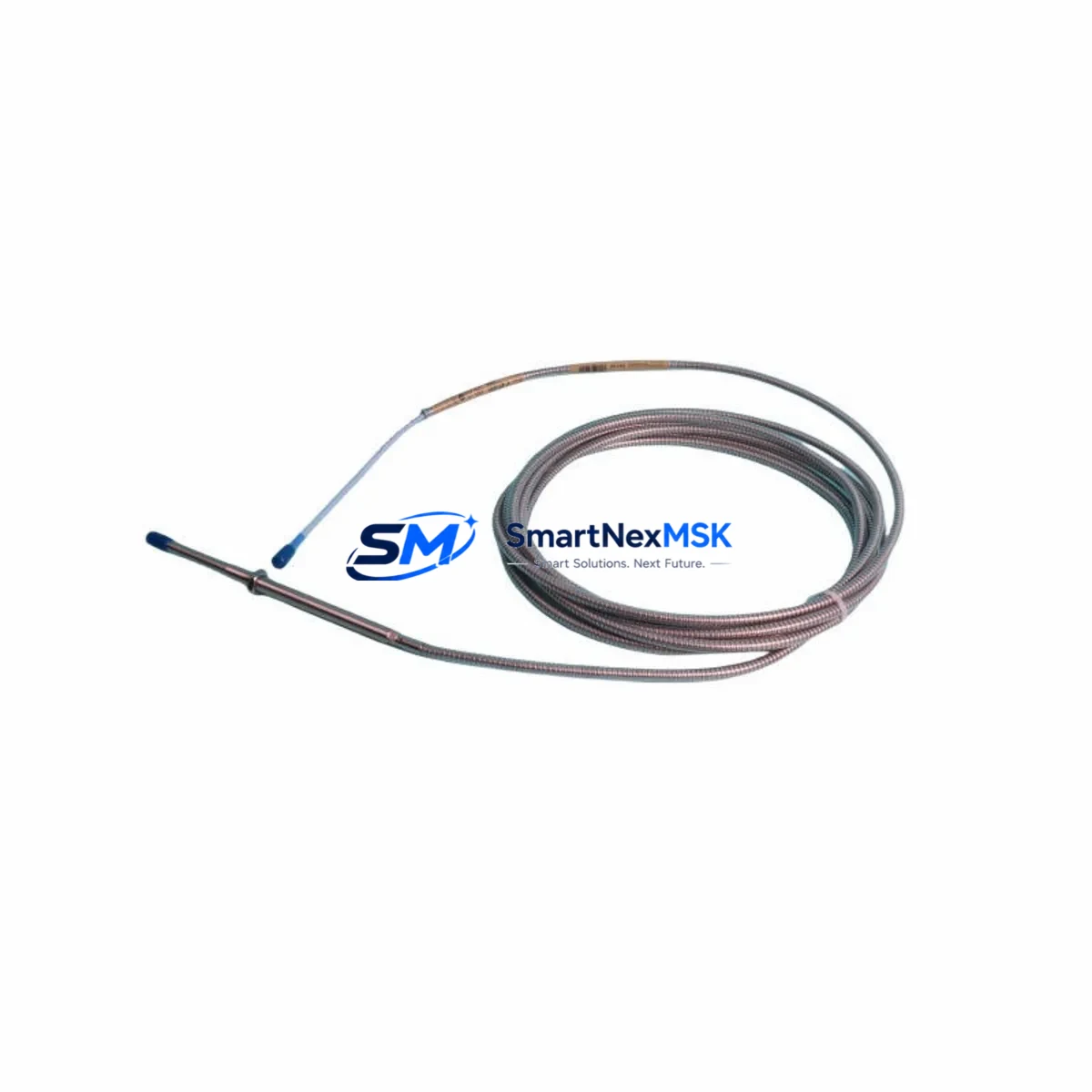
The Bently Nevada 330104-11-22-10-02-CN is an 8mm eddy-current proximity transducer engineered for the 3300 XL Series monitoring platform. Designed for continuous shaft vibration, axial position, and Keyphasor signal measurement, this unit is a direct retrofit replacement for aging or discontinued transducer assemblies in rotating machinery protection systems. Whether you are modernizing a turbine control cabinet, replacing a failed sensor in a compressor train, or migrating from an earlier 3300 Series rack to the current 3300 XL architecture, the 330104-11-22-10-02-CN delivers verified electrical compatibility and dimensional interchangeability with minimal re-engineering.
This transducer operates within the standard Bently Nevada 3300 XL signal chain, interfacing directly with the 3300 XL 8mm Extension Cable and the dedicated 3300 XL Proximitor Sensor. The output signal is a DC voltage proportional to the gap between the probe tip and the observed target surface, making it fully compatible with existing 3500 Series rack monitors, 3300 Series rack monitors, and third-party vibration monitoring systems that accept standard -24 VDC eddy-current transducer outputs. No firmware changes or signal conditioning modifications are required when replacing a like-for-like unit in an established installation.
Upgrade Compatibility Table
| Parameter | 330104-11-22-10-02-CN Specification | Retrofit Notes |
|---|---|---|
| Probe Diameter | 8 mm | Matches standard 3300 XL 8mm bore adapters; no machining required |
| Cable Length (Probe) | 1.0 m (integral) | Verify extension cable length matches existing conduit run; use 330130-080-00-00 extension if needed |
| Proximitor Interface | 3300 XL Proximitor Sensor | Compatible with 330180-X1-05 and 330180-X1-10 Proximitor models |
| Supply Voltage | -24 VDC (nominal) | Confirm rack power supply capacity; 3500/15 Power Supply or equivalent required |
| Output Range | -2 VDC to -18 VDC | Matches 3500 Series monitor input range; no scaling adjustment needed |
| Target Material | AISI 4140 steel (standard) | Verify shaft material; non-standard alloys require scale factor correction in 3500/42M monitor |
| Connector Type | Integral coaxial (CN) | CN suffix denotes Chinese market connector standard; confirm mating connector at junction box |
| Communication Compatibility | Analog DC voltage (passive) | Compatible with 3500 Series, 3300 Series, and third-party DCS/PLC analog input cards |
| Installation Standard | API 670 compliant | Suitable for machinery protection on turbines, compressors, pumps, and gearboxes |
| Warranty | 12 Months | Covers manufacturing defects; includes pre-shipment functional test report |
Retrofit Planning for Existing Automation Systems
Successful integration of the 330104-11-22-10-02-CN into an existing machinery protection system requires a structured pre-installation review. Begin by auditing the current rack configuration. In a typical 3500 Series rack, the transducer signal passes through the 3300 XL Extension Cable into the 3300 XL Proximitor Sensor, which then feeds a conditioned -24 VDC signal to the 3500/42M Proximitor, Velocity, and Acceleration Monitor or the 3500/40M Proximitor and Velocity Monitor. Confirm that the existing Proximitor model is compatible with the 8mm probe system before ordering.
Terminal wiring at the junction box must be verified against the original installation drawing. The 330104-11-22-10-02-CN uses a standard coaxial signal path; the center conductor carries the transducer output and the shield is the signal return. When replacing a unit in a live system, ensure the 3500/15 Power Supply or the 3500/05 Rack Interface Module is de-energized at the relevant channel before disconnecting the coaxial connector. Failure to do so can introduce transient voltages that trigger spurious alarms on adjacent channels monitoring the same shaft.
For installations where the original probe was mounted in a custom adapter or bearing housing, measure the existing gap voltage before removal. Record the static gap reading from the 3500 Series operator display or from the connected DCS analog input — typically a Honeywell C300 Controller or an Emerson DeltaV M-Series I/O card in petrochemical applications. This baseline reading allows the commissioning engineer to set the new probe to the identical gap during reinstallation, preserving the original alarm and danger setpoints without requiring a full vibration survey.
Where the control system uses a Modbus RTU or HART communication link to relay vibration data to a supervisory SCADA platform, no protocol changes are required. The 3500 Series rack handles all signal conditioning and communication; the transducer itself is a passive analog device. However, if the site is migrating from a legacy 3300 Series rack to a new 3500 Series rack as part of a broader control system upgrade, the I/O mapping in the DCS must be updated to reflect the new rack slot addresses. Coordinate this change with the 3500 System Configuration Software (3500 Rack Configuration) before the cutover window to avoid extended downtime.
In applications where the 330104-11-22-10-02-CN is being added as part of an I/O expansion — for example, adding a second Keyphasor measurement point to an existing turbine train — verify that the 3500 rack has an available slot for an additional 3500/42M monitor card and that the 3500/15 Power Supply has sufficient current headroom. Each 8mm transducer system draws approximately 10 mA from the -24 VDC bus; a fully loaded rack with 16 monitor cards can approach the power supply’s rated output, and adding channels without a load audit risks nuisance trips on the power supply’s overcurrent protection.
Downtime Control During System Migration
Minimizing unplanned downtime during a proximity transducer replacement is a primary concern in continuous-process industries. For critical machinery such as steam turbines, gas compressors, and boiler feed pumps, a structured hot-swap procedure is recommended wherever the process permits a brief bypass window. Before removing the 330104-11-22-10-02-CN’s predecessor unit, coordinate with the control room to place the affected monitor channel in bypass mode using the 3500 Series front-panel keyswitch or through the 3500 Rack Configuration Software. This prevents a spurious shutdown signal from reaching the Emergency Shutdown System (ESD) or the Safety Instrumented System (SIS) during the physical swap.
Preserve the original program logic in the connected PLC or DCS. If the vibration monitor’s relay outputs are wired into a Rockwell Automation ControlLogix or Allen-Bradley PLC-5 safety interlock, document the rung logic associated with the vibration trip before any wiring changes. The transducer replacement itself does not alter the PLC program, but a gap-setting error that causes the new probe to output a voltage outside the expected range can trigger an unintended trip if the bypass is removed prematurely.
After physical installation, perform a static gap check using a calibrated digital voltmeter at the Proximitor output terminals. The target gap voltage for an 8mm probe on AISI 4140 steel is typically -10.4 VDC at a 2.0 mm gap. Adjust the probe axial position until this reading is achieved, then lock the probe in place with the locknut and apply thread-locking compound as specified in the Bently Nevada installation manual. Remove the monitor bypass only after confirming the gap voltage is stable and within the OK relay’s acceptance window. Document the as-left gap voltage in the site maintenance record for future reference.
For sites where a full rack replacement is being performed simultaneously — for example, retiring an end-of-life 3300 Series rack and installing a new 3500 Series rack — plan the cutover during a scheduled maintenance outage. Pre-configure the new rack offline using 3500 Rack Configuration Software, import the existing alarm setpoints, and perform a bench-level functional test before the outage begins. This approach reduces the in-field configuration time to less than two hours for a standard eight-channel rack, keeping the machinery offline window within a typical planned maintenance schedule.
Retrofit Support FAQ
Q1: Is the 330104-11-22-10-02-CN a direct drop-in replacement for earlier 330104 series probes?
Yes. The 330104 family shares a common 8mm probe body and coaxial signal interface. The -11-22-10-02-CN suffix specifies the cable configuration, connector type, and market variant. Verify that the extension cable part number and Proximitor model in your installation match the 8mm system specification. If the existing extension cable is a 330130 series unit, it is fully compatible with the 330104-11-22-10-02-CN without modification.
Q2: What wiring checks are required before installation?
Inspect the coaxial cable run from the junction box to the Proximitor for continuity and insulation resistance. A damaged cable shield is the most common cause of elevated noise on the vibration signal after a probe replacement. Measure shield-to-center-conductor resistance; it should be greater than 100 MΩ. Also verify that the junction box terminal block is free of corrosion and that the coaxial connector’s center pin is not recessed or damaged. Replace the extension cable — typically a 330130-080-00-00 or equivalent — if any anomaly is found.
Q3: How is compatibility with third-party DCS analog input cards verified?
The 330104-11-22-10-02-CN outputs a standard -2 VDC to -18 VDC analog signal from the Proximitor. Any DCS analog input card rated for -20 VDC to 0 VDC input range is electrically compatible. Common compatible cards include the Honeywell HLAI FTA, the Emerson DeltaV 8-channel AI card, and the Yokogawa CENTUM VP analog input module. Confirm the input impedance of the DCS card is greater than 10 kΩ to avoid loading the Proximitor output. No signal conditioning or isolator is required for standard installations.
Q4: What does the 12-month warranty cover, and is a test report included?
The 12-month warranty covers all manufacturing defects in materials and workmanship from the date of shipment. Each unit undergoes a pre-shipment functional test that verifies output linearity, gap sensitivity (V/mm), and connector integrity. A test report is available upon request and can be provided with the shipment documentation. The warranty does not cover damage resulting from incorrect installation, mechanical impact, or operation outside the specified supply voltage range. For warranty claims, contact sales@smartnexmsk.com with the unit serial number and a description of the fault.
© 2026 SMARTNEXMSK. All rights reserved.
Original Source: https://smartnexmsk.com
Contact: sales@smartnexmsk.com | +86 18259474341


