Bently Nevada 330104-15-22-50-02-00 3300 XL Retrofit: Compatible Modernization & Smooth System Upgrade
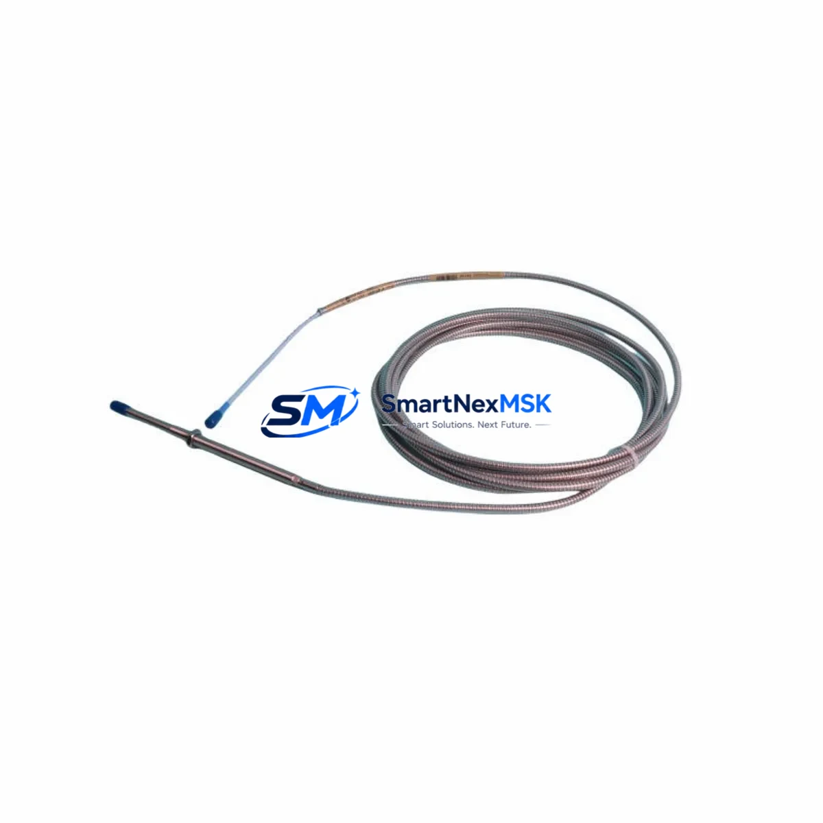
The Bently Nevada 330104-15-22-50-02-00 is an 8mm proximity transducer engineered for the 3300 XL Series continuous machinery monitoring platform. As legacy Bently Nevada installations age and OEM support windows close, plant engineers and reliability teams increasingly turn to verified retrofit-ready replacements to sustain vibration monitoring continuity without triggering full system overhauls. This unit delivers a direct, drop-in upgrade path for facilities operating 3300 XL monitors, 3300 XL API 670 monitors, and associated rack assemblies where the original transducer has reached end-of-life or is no longer available through standard distribution channels.
Whether you are managing a planned turnaround, responding to an unplanned trip, or executing a phased modernization of your rotating machinery protection system, the 330104-15-22-50-02-00 provides the dimensional, electrical, and signal compatibility required to restore full monitoring capability with minimal downtime exposure.
Upgrade Compatibility Table
| Parameter | Specification / Compatibility Note |
|---|---|
| SKU / Part Number | 330104-15-22-50-02-00 |
| Series Compatibility | Bently Nevada 3300 XL Series |
| Transducer Type | 8mm Eddy-Current Proximity Transducer |
| Thread / Mounting | M10 x 1.0 thread; compatible with standard 3300 XL armored extension cable and driver |
| Cable / Connector Interface | Compatible with 330130 series extension cables and 3300 XL drivers (e.g., 330180, 330190) |
| Signal Output | -18 VDC nominal bias; linear range per OEM specification |
| Communication Compatibility | Passive analog; integrates with 3300 XL monitor cards and System 1 software |
| Installation Requirement | Verify gap voltage (typically -10.0 VDC ±0.5 V at nominal gap); recalibrate after installation |
| Replacement Recommendation | Direct drop-in for 330104-15-22-50-02-00; verify driver and extension cable part numbers before ordering |
| Commissioning Focus | Gap setting, bias voltage check, OK relay verification, and System 1 channel confirmation |
| Warranty | 12-Month Warranty — covers manufacturing defects and functional performance |
Retrofit Planning for Existing Automation Systems
Successful retrofit of the 330104-15-22-50-02-00 into an operating plant environment requires a structured review of the surrounding monitoring chain. The transducer does not operate in isolation — it functions as part of a three-component measurement chain that includes the extension cable and the driver (oscillator-demodulator). Before scheduling the replacement, confirm that the installed 330130 series armored extension cable is undamaged and that its total cable length matches the driver calibration. If the extension cable shows signs of jacket degradation or connector corrosion, replacing it alongside the transducer during the same maintenance window eliminates a second outage.
The driver module — commonly a 330180-91-00 or 330190-50-05-00 depending on rack configuration — must be verified for compatibility with the replacement transducer’s sensitivity specification (typically 200 mV/mil or 7.87 V/mm). Mismatched sensitivity between the transducer and driver will produce incorrect vibration amplitude readings and may cause nuisance trips or, more critically, missed alarm conditions on the 3300 XL monitor card.
Within the 3300 XL rack, confirm the monitor card slot assignment and channel address before pulling the old transducer. The 3300 XL 16-channel monitor and the 3300 XL API 670 monitor both support field-configurable channel parameters through the rack’s configuration software. If the rack also houses a 3300 XL Keyphasor module, verify that the phase reference signal is unaffected by the transducer swap, particularly on machines where the Keyphasor probe and the radial vibration probes share a common conduit or junction box.
For facilities running Bently Nevada System 1 condition monitoring software, the channel configuration database should be reviewed after the physical installation. System 1 stores transducer scale factors, full-scale ranges, and alarm setpoints at the channel level. A replacement transducer with a different sensitivity or gap range may require a configuration update in System 1 to maintain accurate trend data and alarm integrity. Export the existing channel configuration before the outage so that the baseline can be restored quickly if needed.
Terminal wiring at the I/O terminal block or junction box should be documented with photographs before disconnection. The 3300 XL system uses a defined terminal assignment for the transducer signal (TIP), shield (SHD), and common (COM) conductors. Incorrect rewiring is one of the most common sources of post-installation faults and can be avoided with a simple pre-outage wiring audit. If the installation uses a 3300 XL field wiring termination panel, confirm that the panel’s terminal strip is clean and that no corrosion has migrated from the field cable into the rack enclosure.
Power supply capacity within the control cabinet should also be confirmed. The 3300 XL rack draws regulated -24 VDC for transducer excitation. If the rack power supply — such as a 3300 XL power supply module — is already operating near its rated output current, adding a replacement transducer without auditing the total load may cause supply droop that affects all channels in the rack. A brief load calculation before the outage prevents this scenario.
Finally, if the retrofit is part of a broader migration from an older Bently Nevada 3300 Series (non-XL) rack to the 3300 XL platform, note that the physical transducer form factor is compatible, but the monitor card firmware, configuration software, and communication interface (typically RS-232 or Ethernet to System 1) will require separate commissioning steps. In this scenario, the 330104-15-22-50-02-00 can serve as the transducer foundation for the new rack while the monitor cards, power supply, and communication gateway are upgraded in parallel.
Downtime Control During System Migration
Minimizing production impact during a transducer replacement on a critical rotating machine requires pre-outage preparation that compresses the actual work window to the shortest defensible duration. The following approach is recommended for facilities where the monitored machine — a compressor, turbine, pump, or fan — cannot be taken offline for extended periods.
Before the outage, stage all replacement components at the work site: the 330104-15-22-50-02-00 transducer, the appropriate extension cable if being replaced, a calibrated gap-setting tool or feeler gauge, a digital voltmeter for bias voltage verification, and a copy of the channel configuration export from System 1. Confirm with the control room that the 3300 XL monitor channel will be placed in bypass mode during the swap to prevent a spurious trip from propagating to the machine protection logic.
During the outage, follow a defined sequence: isolate the channel in bypass, disconnect the field cable at the junction box, remove the old transducer, install the replacement, set the gap to the specified nominal value, reconnect the field cable, verify bias voltage at the monitor card terminal, release the bypass, and confirm the OK relay status and System 1 channel health. This sequence, when rehearsed, can typically be completed in under 60 minutes for a single-channel replacement on an accessible machine.
Original program logic in the 3300 XL monitor is stored in non-volatile memory within the monitor card and is not affected by a transducer swap. However, if the replacement transducer has a different sensitivity specification than the original, the full-scale range and alarm setpoints stored in the monitor card configuration may need to be updated. This update should be performed through the rack’s configuration interface before the bypass is released, not after, to ensure that the machine is protected at the correct alarm thresholds from the moment monitoring is restored.
For facilities with HMI screens displaying vibration trends from the 3300 XL system, confirm with the control room operator that the channel reading is within the expected baseline range after the bypass is released. A sudden step change in the displayed vibration value — even within alarm limits — should be investigated before the outage is formally closed, as it may indicate a gap setting error or a wiring polarity issue that will affect long-term trend data quality.
Retrofit Support FAQ
Q1: Is the 330104-15-22-50-02-00 a direct replacement for the original Bently Nevada part?
Yes. This unit is a verified retrofit-ready replacement for the original 330104-15-22-50-02-00 proximity transducer. It matches the dimensional, electrical, and signal specifications of the OEM part and is compatible with the 3300 XL Series monitoring platform. No mechanical modification to the probe holder or conduit is required.
Q2: What commissioning steps are required after installation?
After physical installation, set the transducer gap to the nominal value specified for your application (typically 1.0 mm / 40 mil for radial vibration on most rotating machinery). Verify the bias voltage at the monitor card terminal (target: -10.0 VDC ±0.5 V). Confirm the OK relay is energized and that System 1 shows a healthy channel status. If the sensitivity specification of the replacement differs from the original, update the channel scale factor in the monitor card configuration before releasing the bypass.
Q3: Does the replacement affect the existing wiring and terminal connections?
No changes to the terminal wiring scheme are required. The 330104-15-22-50-02-00 uses the same TIP/SHD/COM conductor assignment as the original. Document the existing wiring before disconnection and verify continuity after reconnection. If the extension cable is being replaced simultaneously, confirm that the new cable length matches the driver calibration range.
Q4: What warranty coverage is provided, and has the unit been tested before shipment?
Every unit is subject to functional testing prior to shipment, including bias voltage output verification and continuity checks. A 12-month warranty is provided from the date of shipment, covering manufacturing defects and functional performance under normal operating conditions. Warranty claims are supported by our technical team at sales@smartnexmsk.com.
© 2026 SMARTNEXMSK. All rights reserved.
Original Source: https://smartnexmsk.com
Contact: sales@smartnexmsk.com | +86 18259474341


