Bently Nevada 330105-02-12-05-02-00 Retrofit-Ready Proximity Probe for 3300 XL Control Systems
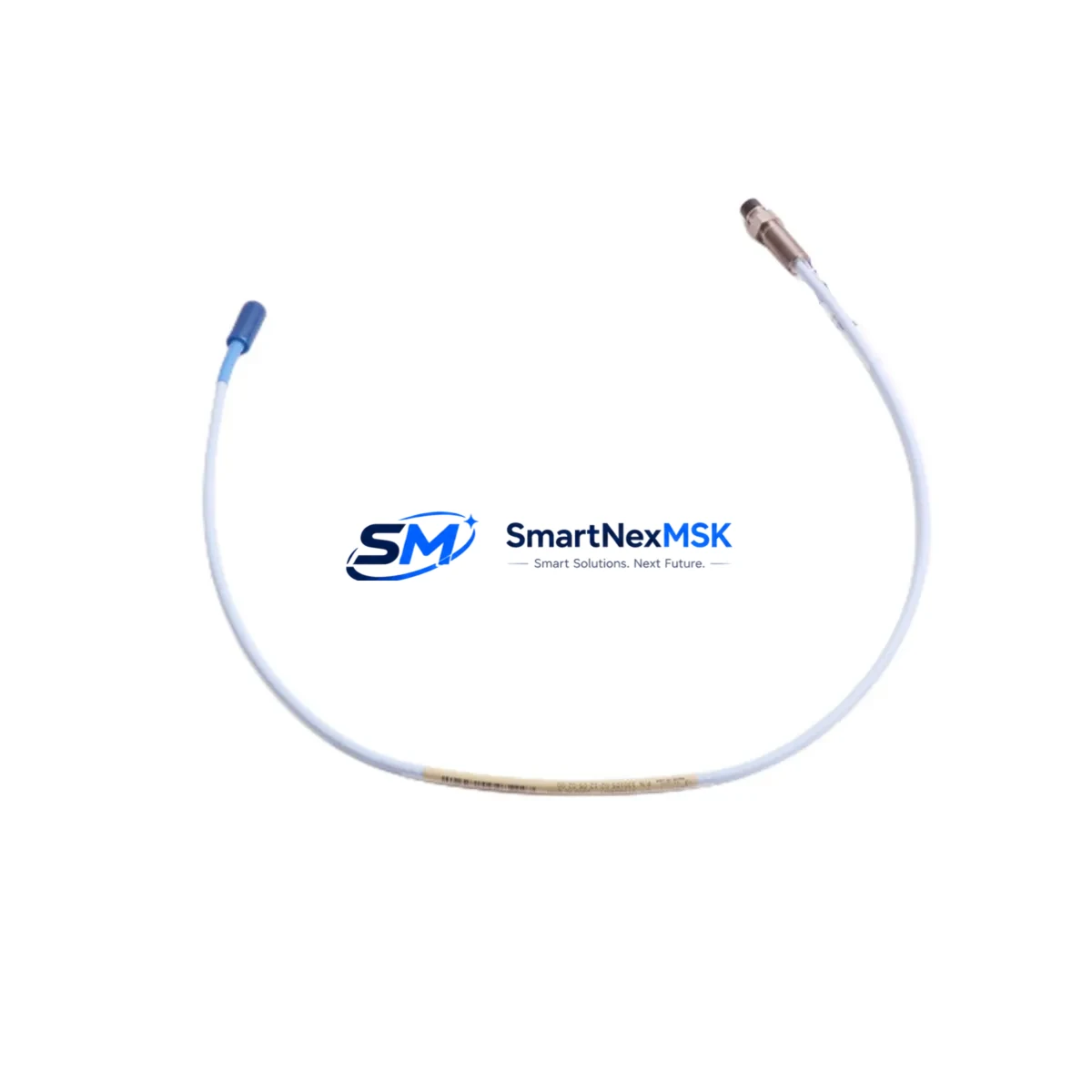
The Bently Nevada 330105-02-12-05-02-00 is an 8mm eddy-current proximity probe engineered for direct retrofit into existing 3300 XL Series vibration monitoring installations. As original 3300 XL probes reach end-of-life or become unavailable through standard supply channels, plant reliability engineers and maintenance teams rely on the 330105-02-12-05-02-00 as a verified drop-in replacement that restores measurement loop integrity without requiring rack redesign, PLC reprogramming, or HMI reconfiguration. Whether the application involves turbine shaft displacement monitoring, compressor radial vibration measurement, or axial position sensing on a critical rotating machine, this probe delivers the dimensional accuracy, output linearity, and environmental durability demanded by continuous industrial operation.
The 330105-02-12-05-02-00 is fully compatible with the 3300 XL transducer system architecture. It pairs directly with the 3300 XL 8mm Extension Cable and the 3300 XL Proximitor System driver electronics, maintaining the standard -24 VDC bias voltage and 200 mV/mil (7.87 V/mm) scale factor that the 3500/40M Proximitor/Seismic Monitor and 3500/42M Proximitor/Seismic Monitor expect at their signal conditioning inputs. Alarm setpoints, danger thresholds, and buffered output signals remain valid after replacement without recalibration of the monitoring rack, significantly reducing the engineering effort and risk associated with a sensor swap on a live protection system.
Upgrade Compatibility Table
| Parameter | 330105-02-12-05-02-00 (This Unit) | Legacy 3300 XL Equivalent |
|---|---|---|
| Sensor Tip Diameter | 8 mm | 8 mm |
| Probe Cable Length | 0.5 m integral cable | 0.5 m integral cable |
| Extension Cable Length | 1.2 m (via 3300 XL Extension Cable) | 1.2 m |
| Scale Factor | 200 mV/mil (7.87 V/mm) | 200 mV/mil (7.87 V/mm) |
| Bias Voltage Output | -24 VDC (nominal) | -24 VDC (nominal) |
| Supply Voltage | -24 VDC ± 1 VDC | -24 VDC ± 1 VDC |
| Compatible Driver | 3300 XL Proximitor System | 3300 XL Proximitor System |
| Rack Compatibility | 3500 Series Monitoring Rack | 3500 / 3300 Series Rack |
| Installation Interface | Standard 3300 XL connector | Standard 3300 XL connector |
| Communication Protocol | Analogue (voltage / 4–20 mA) | Analogue (voltage / 4–20 mA) |
| Replacement Recommendation | Direct drop-in; verify gap voltage post-installation | — |
| Commissioning Checkpoint | Gap voltage, scale factor, alarm setpoint confirmation | — |
| Warranty | 12 Months | — |
Retrofit Planning for Existing Automation Systems
A successful retrofit centred on the 330105-02-12-05-02-00 begins with a thorough pre-outage engineering review. Technicians should retrieve the existing loop drawing to confirm the installed extension cable part number — typically a 330130-045-00-00 or 330130-080-00-00 3300 XL Extension Cable — and verify that the combined cable length between the probe, extension cable, and Proximitor driver falls within the qualified range for the 3300 XL transducer system. Exceeding the qualified total cable length degrades the linear operating range and introduces measurement error that a simple bias voltage check will not detect.
At the control cabinet level, engineers should inspect the 3500 Series rack backplane to confirm that the channel card assigned to the affected measurement point is a 3500/40M or 3500/42M module and that the I/O termination block — often a 3500/20 Rack Interface I/O Module — is correctly wired for the probe’s differential input. If the plant is operating an older 3300 Series rack rather than the 3500 platform, the retrofit may also require evaluation of the 3300/55 Dual Proximitor Monitor or the 3300/16 Dual Voting Logic Unit to confirm that the replacement probe’s output characteristics remain within the card’s input acceptance window.
For plants integrating vibration data into a DCS or safety instrumented system, the 330105-02-12-05-02-00’s analogue output feeds directly into the existing 4–20 mA input channels of the DCS I/O marshalling cabinet without protocol conversion. However, if the site is migrating from a standalone vibration panel to a networked architecture using the 3500 System Gateway or a Modbus/TCP interface card, the commissioning team must verify that the channel address mapping in the gateway configuration matches the physical slot assignment in the 3500 rack. HMI screens built on legacy vibration tag names should be reviewed and updated to reflect any channel renumbering introduced during the rack migration, preventing nuisance alarms or missed danger indications during the first post-retrofit run.
Power supply capacity is a frequently overlooked constraint in probe retrofit projects. Each 3300 XL Proximitor driver draws a defined current from the -24 VDC bus. When multiple probes are being replaced simultaneously — for example, during a full turbine train overhaul that also involves swapping the 3500/15 Power Supply Module or adding new I/O cards — the total current budget of the rack power supply must be recalculated before energisation. Failure to account for the cumulative load of new probes, replacement communication modules, and any added 3500/92 Ethernet Interface cards can result in supply voltage droop that shifts probe bias voltage outside the qualified operating window and triggers false alarms or spurious trips.
Where the retrofit scope extends to the programming cable and laptop interface, technicians using the System 1 Evolution software or the Rack Configuration Software should confirm that the 3500/20 I/O module configuration file reflects the correct probe type and cable length selection. An incorrect software configuration — even with a physically correct probe installed — will cause the rack to apply the wrong calibration curve, producing systematic measurement error across the entire channel range.
Downtime Control During System Migration
Minimising unplanned downtime during a probe replacement requires a structured pre-outage preparation protocol. Before the maintenance window opens, the replacement 330105-02-12-05-02-00 should be bench-tested against a reference target to confirm bias voltage and scale factor are within specification. This pre-shipment functional test is included as part of our standard 12-month warranty coverage, eliminating the risk of installing a non-conforming unit and discovering the fault only after the machine is back on turning gear.
During the outage, the original PLC or DCS program logic should not be modified. The 330105-02-12-05-02-00 is designed to restore the measurement loop to its original operating state, so alarm setpoints, danger thresholds, and trip logic stored in the 3500 rack or the upstream safety PLC remain valid. The technician’s task is limited to physical probe removal, installation of the replacement unit, gap adjustment to the target value specified on the original loop calibration sheet, and confirmation that the buffered output signal at the 3500 rack front panel matches the expected voltage for the measured gap. Once the gap voltage is confirmed, the channel can be returned to service and the machine brought back online without any changes to the control program, HMI configuration, or historian tag mapping.
For sites where continuous operation is critical and a cold swap is not acceptable, a temporary bypass strategy using the 3500 rack’s channel inhibit function allows the affected measurement point to be placed in bypass while the probe is exchanged, preserving the protection logic on all remaining channels and preventing a spurious trip during the swap. The inhibit status should be logged, time-stamped, and cleared immediately upon confirmation of the new probe’s correct operation to maintain the integrity of the machinery protection system.
Retrofit Support FAQ
Q1: Is the 330105-02-12-05-02-00 a direct replacement for the original 3300 XL 8mm proximity probes?
Yes. The 330105-02-12-05-02-00 is dimensionally and electrically compatible with the 3300 XL transducer system. It uses the same 8mm tip geometry, the same connector interface, and produces the same 200 mV/mil scale factor and -24 VDC nominal bias voltage as the original 3300 XL probes. No modifications to the extension cable, Proximitor driver, or rack wiring are required for a standard replacement.
Q2: What wiring checks are required before energising the replacement probe?
Verify that the shield drain wire is terminated at one end only — typically at the Proximitor driver end — to prevent ground loops. Confirm that the connector is fully seated and the locking collar is engaged. Check that the cable is routed away from high-voltage conductors and secured to prevent vibration-induced connector fretting. After energisation, measure the bias voltage at the Proximitor driver’s output terminals and confirm it falls within the qualified linear range for the installed gap.
Q3: How is compatibility with the 3500 Series monitoring rack verified during commissioning?
With the probe installed and the machine stationary, adjust the probe gap to the target value specified in the original calibration record — typically 50 mils (1.27 mm) for most shaft rider applications. Read the bias voltage at the 3500/40M or 3500/42M channel card’s buffered output. The reading should match the expected value from the 3300 XL transducer system calibration curve within ±0.5 VDC. If the reading is outside this tolerance, recheck the gap, inspect the extension cable for damage, and confirm the Proximitor driver part number matches the probe’s qualified driver list.
Q4: What does the 12-month warranty cover, and what documentation is provided?
Every 330105-02-12-05-02-00 supplied by SMARTNEXMSK is covered by a 12-month warranty against manufacturing defects and functional non-conformance from the date of shipment. Each unit is shipped with a functional test record confirming bias voltage and scale factor compliance. In the event of a warranty claim, we provide advance replacement to minimise site downtime, and the defective unit is returned for root-cause analysis. Warranty claims are processed within 48 hours of receipt of the defective unit.
© 2026 SMARTNEXMSK. All rights reserved.
Original Source: https://smartnexmsk.com
Contact: sales@smartnexmsk.com | +86 18259474341


