Bently Nevada 330106-05-30-05-12-05 Retrofit-Ready 3300 XL Proximity Transducer System
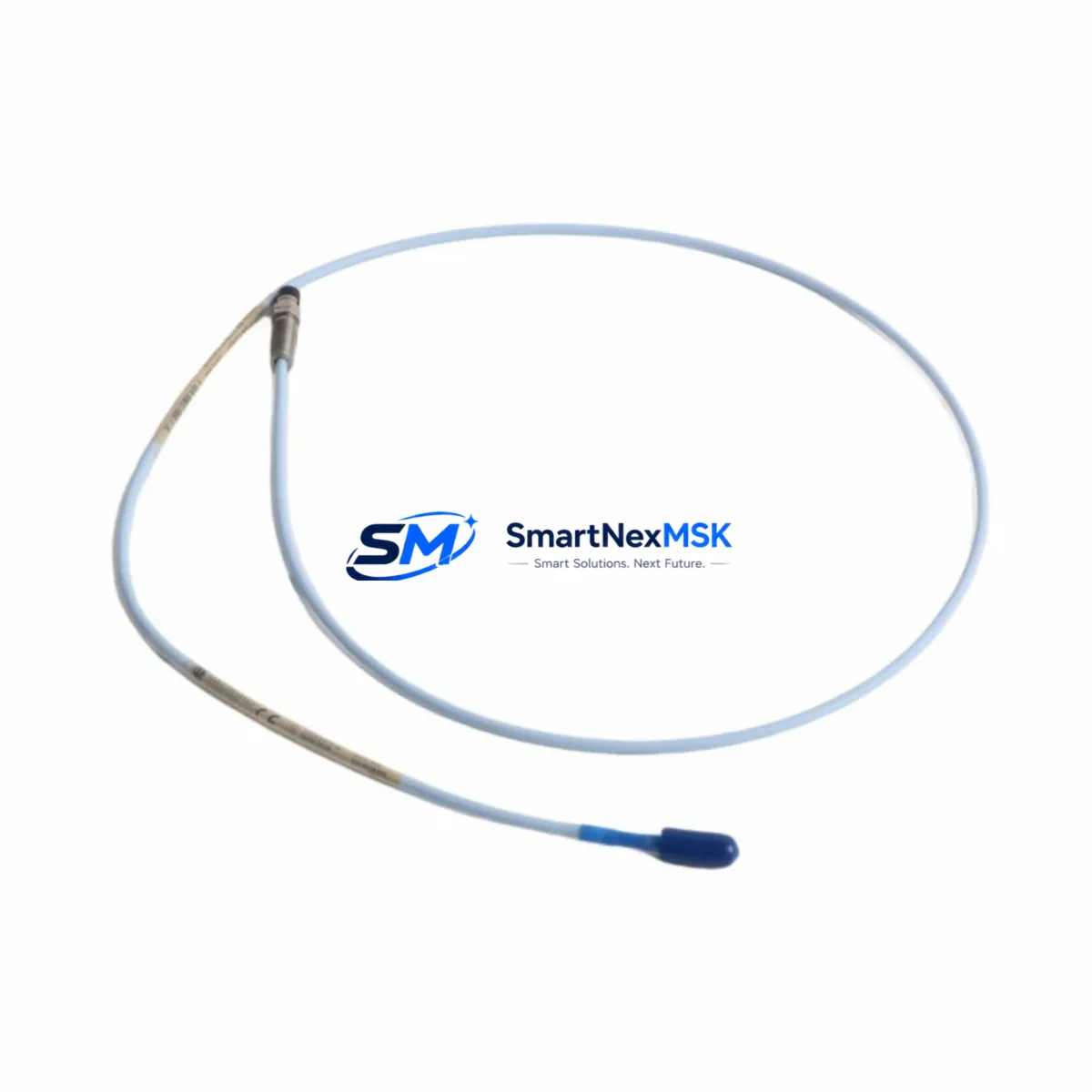
The Bently Nevada 330106-05-30-05-12-05 is an 8mm proximity transducer system engineered for the 3300 XL platform — one of the most widely deployed machinery protection and condition monitoring architectures in rotating equipment facilities worldwide. As original Bently Nevada 3300 XL components approach end-of-life or become increasingly difficult to source through OEM channels, the 330106-05-30-05-12-05 remains a critical retrofit solution for plants seeking to extend the operational life of their existing monitoring infrastructure without committing to a full system replacement.
This transducer system is designed for direct drop-in compatibility with 3300 XL monitor racks, including the 3300/16 and 3300/20 series monitor cards. The 8mm probe tip, 5-metre extension cable, and -5V to -24V output range conform to the standard Bently Nevada signal chain, ensuring that existing 3300 XL proximitor/driver assemblies, field wiring, and monitor channel configurations remain fully intact during the swap. Engineers performing the replacement should verify the existing proximitor supply voltage, confirm the gap voltage at the installed probe tip (typically -10V ±1V at the nominal air gap), and validate the output sensitivity against the monitor’s configured scale factor before returning the channel to service.
Upgrade Compatibility Table
| Parameter | 330106-05-30-05-12-05 (This Unit) | Notes / Retrofit Guidance |
|---|---|---|
| Probe Diameter | 8mm | Matches standard 3300 XL 8mm probe mounting hardware |
| Extension Cable Length | 5m (16.4 ft) | Verify cable routing clearance in existing conduit |
| Driver/Proximitor | 3300 XL 8mm Proximitor | Compatible with 330180 series proximitor modules |
| Output Voltage Range | -5V to -24V DC | Confirm monitor input range on 3300/16 or 3300/20 card |
| Sensitivity | 200 mV/mil (7.87 V/mm) | Match to monitor channel scale factor setting |
| Installation Thread | M10 x 1.0 | Verify existing probe holder thread specification |
| Communication Protocol | Analogue (4–20 mA / voltage) | No protocol migration required; direct signal replacement |
| Monitor Compatibility | 3300/16, 3300/20, 3300/46, 3300/55 | Confirm slot assignment and channel address in rack |
| Replacement Recommendation | Direct drop-in for 330106 series | No firmware or configuration changes required |
| Commissioning Focus | Gap voltage, sensitivity, alarm setpoints | Re-verify vibration and position alarm thresholds post-swap |
| Warranty | 12 Months | Covers manufacturing defects; includes pre-shipment functional test |
Retrofit Planning for Existing Automation Systems
Facilities running legacy Bently Nevada 3300 XL machinery protection systems typically operate the transducer system alongside a broader suite of condition monitoring and control hardware. When planning a retrofit around the 330106-05-30-05-12-05, maintenance engineers should account for the full signal chain from the probe tip through to the control room. The 330180-91-00 proximitor module, which conditions the raw eddy-current signal from the 8mm probe, should be inspected for output drift and recalibrated if the unit has been in service for more than five years. In racks where multiple channels share a common power supply, the 3300/05 power supply module should be load-tested to confirm it can sustain the additional draw from a freshly installed transducer without voltage sag affecting adjacent monitor channels.
For plants that have integrated their 3300 XL rack into a DCS or safety instrumented system via the 3500/92 communication gateway or a Modbus TCP interface card, the channel mapping and tag assignments in the host system should be reviewed before the transducer is swapped. Although the 330106-05-30-05-12-05 replacement does not alter the analogue output characteristics, any gap in signal continuity during the swap may trigger a channel fault alarm in the DCS historian or cause a spurious trip in a safety logic solver if the monitor is not placed in bypass mode prior to work commencement.
In control cabinets where the 3300 XL rack is co-located with a PLC-based sequence controller — such as an Allen-Bradley ControlLogix or Siemens S7-300 — the vibration and position analogue inputs feeding the PLC’s analogue input module should be confirmed against the I/O list before and after the swap. If the plant uses a 3300/46 dual-voting monitor card for overspeed or thrust position protection, both voting channels must be verified independently after the new transducer is installed. The HMI faceplate associated with the monitored machine should also be checked to confirm that the gap voltage and vibration trend displays are reading correctly from the newly installed probe, and that any historical baseline data stored in the System 1 condition monitoring software is updated to reflect the new probe installation date and gap setting.
Where the retrofit involves replacing multiple transducer systems across a machine train — for example, on a compressor with both radial vibration and axial position monitoring — it is advisable to stage the replacement channel by channel, returning each channel to normal operation and verifying alarm setpoints before proceeding to the next. This approach minimises the risk of a simultaneous multi-channel fault condition and allows the commissioning engineer to isolate any wiring or grounding issues to a specific probe location. Spare 330130-080-00-00 armoured extension cables and 330105-02-12-05-02-00 probe assemblies should be staged in the field prior to commencing work to avoid delays if a cable is found to be damaged during removal.
Downtime Control During System Migration
Minimising unplanned downtime is the primary operational constraint when replacing proximity transducer systems on running or recently shut-down machinery. The 330106-05-30-05-12-05 is supplied pre-tested and gap-verified, which eliminates the most time-consuming step in a field replacement — the initial probe characterisation. Upon receipt, the unit includes a test certificate confirming output linearity across the full measurement range, allowing the commissioning engineer to proceed directly to installation and gap setting without bench verification.
To protect the original control program logic during the swap, the monitor channel should be placed in bypass or inhibit mode using the front-panel keyswitch or via the System 1 software interface before the probe is disconnected. This prevents the monitor from issuing a danger output or triggering a machine trip on the loss of the transducer signal. The existing gap voltage reading should be recorded before removal so that the replacement probe can be set to the same nominal gap, preserving the calibrated measurement range and ensuring that the vibration alarm setpoints remain valid without recalculation.
Field wiring continuity should be verified with a loop resistance check before the new transducer is connected, particularly in installations where the extension cable runs through areas exposed to mechanical vibration, heat, or chemical contamination. Once the replacement probe is installed and the gap voltage confirmed, the channel should be released from bypass mode and the vibration and position readings observed for a minimum of 15 minutes under normal operating conditions before the work permit is closed. All commissioning data — including gap voltage, output voltage at operating speed, and alarm setpoint verification — should be recorded in the plant maintenance management system to support future audits and warranty claims.
Retrofit Support FAQ
Q: Is the 330106-05-30-05-12-05 a direct replacement for all 330106 series transducer systems?
A: The 330106-05-30-05-12-05 is directly interchangeable with other 330106 series configurations that share the same probe diameter (8mm), extension cable length (5m), and proximitor type. Configurations with different cable lengths or probe diameters (e.g., 5mm or 11mm variants) are not interchangeable and require the corresponding part number. Always confirm the full part number from the existing installation records before ordering.
Q: What commissioning steps are required after installation?
A: After mechanical installation, set the probe gap to achieve the nominal gap voltage specified on the monitor channel configuration sheet (typically -10V ±1V for 8mm probes). Verify the output voltage at the proximitor output terminals, confirm the reading on the monitor front panel, and check that the vibration and position values displayed on the HMI are within expected operating ranges. Re-verify all alarm and danger setpoints before releasing the channel from bypass mode.
Q: Does the replacement affect existing wiring or terminal connections?
A: No terminal wiring changes are required. The 330106-05-30-05-12-05 uses the same connector and cable termination standard as the original 330106 series, allowing the existing field wiring at the junction box and monitor rack terminal block to remain undisturbed. Inspect the existing cable connectors for corrosion or mechanical damage before reconnecting.
Q: What does the 12-month warranty cover?
A: The 12-month warranty covers manufacturing defects in materials and workmanship under normal operating conditions. Each unit undergoes a pre-shipment functional test to verify output linearity, sensitivity, and connector integrity. Warranty claims require the original purchase documentation and a description of the fault condition. Units damaged by incorrect installation, overvoltage, or mechanical impact are not covered under the standard warranty terms.
© 2026 SMARTNEXMSK. All rights reserved.
Original Source: https://smartnexmsk.com
Contact: sales@smartnexmsk.com | +86 18259474341


