Bently Nevada 330130-030-00-05 Spare for 3300 XL Automation: Spare Replacement & Industrial Downtime Risk Control
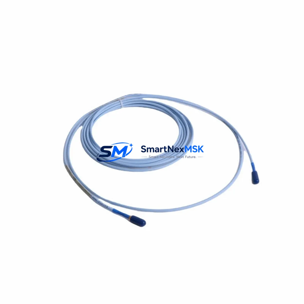
The Bently Nevada 330130-030-00-05 is an original eddy-current proximity transducer engineered for the 3300 XL continuous vibration monitoring system. Designed for critical rotating machinery protection in power generation, petrochemical, oil & gas, and heavy industrial environments, this transducer delivers precise non-contact displacement and vibration measurement essential for turbine, compressor, and pump shaft monitoring. When a proximity transducer fails or drifts out of calibration, the consequences extend beyond a single sensor — the entire vibration monitoring loop is compromised, creating undetected machinery risk and potential unplanned shutdown.
Sourcing a verified original spare for the 330130-030-00-05 is the first step in a disciplined maintenance strategy. This unit ships tested, with full 12-month warranty coverage, and is available for immediate dispatch to minimize your downtime window.
Spare Maintenance Table
| Parameter | Specification |
|---|---|
| Part Number / SKU | 330130-030-00-05 |
| Brand | Bently Nevada |
| Series | 3300 XL Eddy-Current System |
| Product Type | Proximity Transducer |
| Sensing Technology | Eddy-Current (Non-Contact) |
| Cable Length | 3.0 m (integrated extension cable) |
| Tip Diameter | 5 mm |
| Measurement Range | 0–2.0 mm (nominal linear range) |
| Output Signal | –24 VDC bias, analog voltage proportional to gap |
| Supply Voltage | –24 VDC (via 3300 XL proximitor/driver) |
| Operating Temperature | –35°C to +120°C (probe tip) |
| Compatibility | 3300 XL Proximitor/Seismic Monitor, 3300/16 Rack, 3500 Series (with adapter) |
| Installation | M8 threaded probe body, locknut included |
| Application Environment | Turbines, compressors, pumps, gearboxes — oil & gas, power, petrochemical |
| Maintenance Recommendation | Replace as matched set with extension cable and proximitor for optimal calibration |
| Origin | United States |
| Warranty | 12 Months from shipment date |
| Pre-Shipment Testing | Functional output and gap calibration verified before dispatch |
Maintenance Planning for Continuous Operation
A proximity transducer replacement should never be treated as an isolated swap. The 330130-030-00-05 operates as part of a tightly coupled measurement chain, and experienced maintenance engineers know that restoring full system integrity requires inspecting every component in the loop. When replacing this transducer, the following components should be evaluated concurrently:
The 3300 XL Extension Cable (typically 330130-080-00-05 or matched length variant) connects the probe to the proximitor driver. Cable damage, connector corrosion, or impedance mismatch will cause calibration errors even with a new probe installed — always inspect or replace the extension cable as a matched set. The 3300 XL Proximitor/Driver Module (such as the 330180 series) converts the probe’s eddy-current signal into a usable –24 VDC analog output; a drifting or failed proximitor will produce erroneous readings regardless of probe condition. Verify its output voltage at the known gap before closing the loop.
Within the monitoring rack, the 3300/16 Monitor Card or equivalent 3500 Series I/O module processes the transducer signal for alarm and trip logic. Inspect the card for blown fuses, failed optocouplers, or corrupted configuration — particularly after a machinery trip event that may have induced voltage spikes. The rack power supply module feeding the 3300 or 3500 chassis should be checked for output stability; a sagging –24 VDC rail will shift the transducer’s operating point and produce false readings across all channels.
For systems integrated with a DCS or safety PLC, verify the 4–20 mA signal isolator or Zener barrier in the field wiring circuit — these components degrade over time in high-temperature or high-humidity environments and can introduce signal offset. Terminal blocks and field junction boxes in the transducer wiring run should be inspected for loose connections, moisture ingress, and corrosion, especially in outdoor or wash-down areas.
If the machinery protection system feeds an HMI or historian, confirm that the new transducer’s calibration constants are correctly entered and that alarm setpoints reflect the replacement unit’s sensitivity. Finally, review the keyphasor transducer (such as the 330980 series) if phase-referenced vibration analysis is part of your monitoring strategy — a keyphasor that has drifted or been mechanically disturbed will corrupt vector data even after a successful probe replacement.
Stocking these components alongside the 330130-030-00-05 in your critical spare parts inventory ensures that a single-sensor fault does not cascade into a multi-day outage while waiting for secondary parts.
Site Replacement Workflow
Step 1 — Isolation & Lockout: Follow your site LOTO procedure. De-energize the monitoring rack channel associated with the failed transducer. Do not remove the probe while the machinery is running unless your site procedure explicitly permits hot-swap on a non-trip channel.
Step 2 — Gap Measurement & Documentation: Before removing the old probe, record the installed gap (typically 1.0–1.5 mm for most shaft applications). This baseline allows you to set the replacement probe to the same mechanical position and minimizes re-calibration time.
Step 3 — Probe Removal: Loosen the locknut and unthread the 330130-030-00-05 probe body from the bracket. Inspect the bracket threads and probe holder for wear or damage. A damaged holder will prevent repeatable gap setting on the new probe.
Step 4 — Extension Cable Inspection: Disconnect the extension cable at both ends. Inspect the coaxial connectors for bent pins, corrosion, or contamination. If the cable shows any physical damage or the connector is corroded, replace it with the matched-length extension cable before installing the new probe.
Step 5 — New Probe Installation: Thread the replacement 330130-030-00-05 into the bracket. Set the gap to the documented baseline using a feeler gauge or the proximitor output voltage method (–10.0 VDC ≈ 1.0 mm gap for standard 3300 XL calibration). Tighten the locknut to the specified torque.
Step 6 — System Verification: Re-energize the channel. Verify the proximitor output voltage is within the linear range. Confirm the DCS or monitor card is reading correctly and that no spurious alarms are active. Document the as-left gap and output voltage in your maintenance management system.
Step 7 — Return to Service: Clear the LOTO, restore the channel to normal monitoring mode, and notify the control room. Update your spare parts inventory to reflect the consumed unit and initiate a replenishment order to maintain your critical stock level.
This workflow is compatible with legacy 3300 Series installations and current 3500 Series racks using the appropriate adapter, making the 330130-030-00-05 a versatile replacement that supports old-system life extension without requiring a full rack upgrade.
Spare Parts Support FAQ
Q1: Is the 330130-030-00-05 compatible with both the 3300 and 3500 Series monitoring racks?
The 330130-030-00-05 is natively designed for the 3300 XL eddy-current system. It is compatible with 3500 Series racks when used with the appropriate proximitor/driver module and wiring adapter. Confirm your rack model and proximitor part number before ordering to ensure a direct drop-in fit.
Q2: Should the probe, extension cable, and proximitor be replaced as a matched set?
Best practice is to replace the probe and extension cable as a matched set, as the system is factory-calibrated as a unit. If the proximitor shows any output drift or has accumulated significant operating hours, replacing it simultaneously eliminates the risk of residual calibration error and reduces future maintenance interventions.
Q3: How is the unit tested before shipment?
Each 330130-030-00-05 unit undergoes functional output verification and gap calibration check prior to dispatch. Test records are available upon request. The 12-month warranty covers manufacturing defects and functional failures under normal operating conditions from the date of shipment.
Q4: What is the recommended spare parts stocking strategy for critical rotating machinery?
For machinery classified as critical or essential, maintain a minimum of one probe-cable-proximitor set per monitored machine train in your on-site spare parts store. For large fleets or remote sites, a buffer stock of 2–3 units per transducer model is recommended to cover simultaneous failures and extended lead times. Annual inventory audits aligned with planned shutdown schedules ensure stock remains current and components have not exceeded their storage life.
© 2026 SMARTNEXMSK. All rights reserved.
Original Source: https://smartnexmsk.com
Contact: sales@smartnexmsk.com | +86 18259474341


