Bently Nevada 330130-030-01-00 Spare 3300 XL Automation: Spare Parts Replacement & Industrial Downtime Risk Control
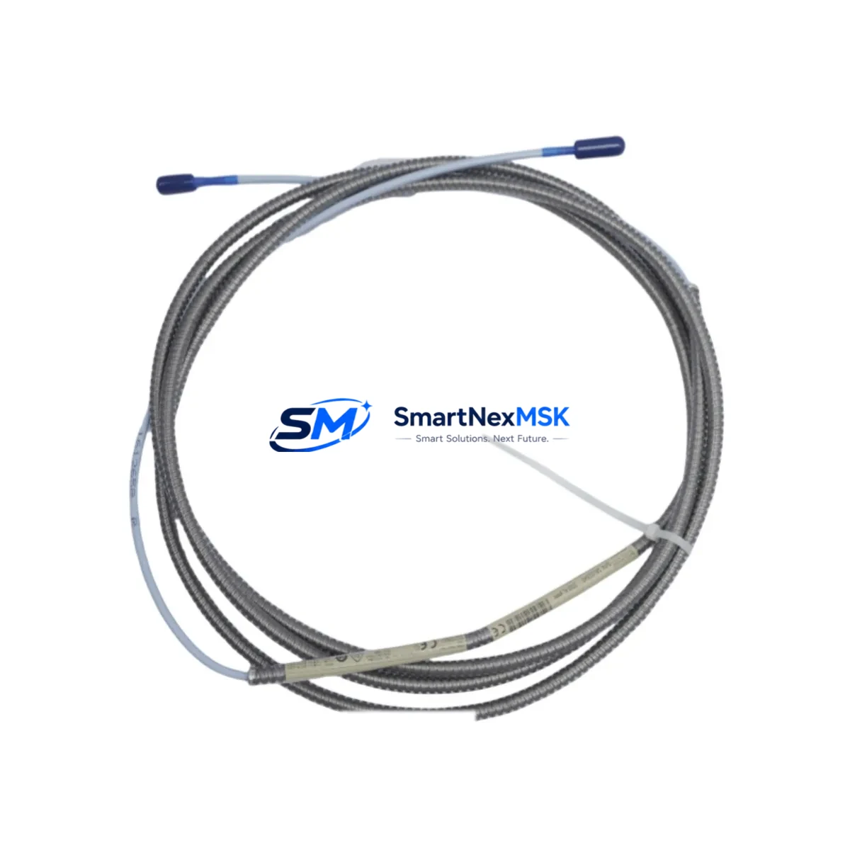
The Bently Nevada 330130-030-01-00 is an original proximity probe extension cable engineered for the 3300 XL Series continuous vibration monitoring system. Designed for rotating machinery protection in power generation, petrochemical, oil & gas, and heavy industrial environments, this extension cable forms the critical signal path between the proximity probe tip and the Bently Nevada 3300 XL monitor rack. Maintaining a verified spare of the 330130-030-01-00 in your site inventory is a fundamental requirement for any maintenance strategy targeting zero unplanned downtime.
For maintenance engineers managing turbine trains, compressor strings, or pump sets equipped with Bently Nevada 3300 XL systems, the extension cable is one of the highest-wear signal components in the proximity measurement loop. Cable jacket degradation, connector corrosion, mechanical damage from vibration fatigue, and chemical exposure in harsh plant environments are the leading causes of signal dropout and false trip events. A pre-qualified replacement unit on the shelf eliminates the multi-day procurement lead time that typically extends forced outages.
Spare Maintenance Table
| Parameter | Specification |
|---|---|
| Part Number / SKU | 330130-030-01-00 |
| Brand | Bently Nevada |
| Series | 3300 XL Proximity System |
| Product Type | Proximity Probe Extension Cable |
| Cable Length | 9 m (30 ft) — standard configuration |
| Connector Type | MIL-spec coaxial, gold-plated, field-mateable |
| System Compatibility | Bently Nevada 3300 XL, 3300/16, 3300/25, 3300/55 monitor modules |
| Probe Compatibility | 330103, 330104, 330105, 330106 series proximity probes |
| Signal Type | Eddy-current proximity, –24 VDC bias, 200 mV/mil sensitivity |
| Operating Temperature | –40 °C to +121 °C |
| Origin | United States |
| Weight | 280 g (approx.) |
| Application Environment | Turbines, compressors, pumps, gearboxes — API 670 compliant installations |
| Maintenance Recommendation | Inspect connectors every 12 months; replace cable if jacket cracking or signal drift detected |
| Warranty | 12 Months — covers manufacturing defects and signal integrity |
| Condition | Original, new or reconditioned; function-tested before shipment |
Maintenance Planning for Continuous Operation
When a 330130-030-01-00 extension cable is flagged for replacement during a planned outage or emergency callout, experienced maintenance engineers treat the event as a trigger for a broader inspection of the entire proximity measurement loop and the associated monitor rack bay. The extension cable does not operate in isolation — its signal integrity depends on the condition of every upstream and downstream component in the measurement chain.
Begin with the 330103 or 330104 proximity probe tip at the machine end. Probe tip gap voltage should be verified with a calibrated gap tool before the new extension cable is terminated. If the probe tip shows mechanical wear, thread damage, or a gap voltage outside the –10 VDC to –18 VDC linear range, replace the probe simultaneously to avoid a repeat outage. Next, inspect the 330180 proximitor / oscillator-demodulator housing. The proximitor converts the raw eddy-current signal to a DC voltage proportional to gap distance; a degraded proximitor will produce erratic readings even with a new cable installed.
At the monitor rack, verify the 3300/16 or 3300/25 radial vibration monitor module input impedance and alarm setpoints. Connector pins on the monitor front panel should be cleaned and inspected for fretting corrosion, particularly in high-vibration environments. If the rack houses a 3300/55 thrust position monitor on the same shaft, cross-check its extension cable and proximitor as part of the same work order — shared outage windows reduce total maintenance cost significantly.
Power supply integrity is equally critical. The 3300/20 power supply module feeding the monitor rack should be load-tested and its output voltage verified at ±24 VDC within tolerance. A marginal power supply will cause intermittent signal noise that is frequently misdiagnosed as a cable fault. Where redundant power is configured, test the automatic changeover function before returning the system to service.
For facilities running System 1 Evolution or legacy System 1 condition monitoring software, confirm that the replacement cable’s signal is correctly mapped to the corresponding channel tag in the historian. A channel mapping error after a cable swap can suppress alarms silently — a risk that is unacceptable in API 670 protection-grade installations. Finally, review the TK-3 or TK-4 termination kit inventory; connector termination kits are consumables that should be stocked alongside every extension cable spare to support field re-termination without additional procurement delays.
Site Replacement Workflow
Step 1 — Isolation and permit: Obtain a hot-work or cold-work permit as applicable. Place the affected monitor channel in bypass mode via the 3300 XL rack front panel or System 1 software to suppress spurious trips during cable removal. Document the existing gap voltage reading before disconnection.
Step 2 — Cable removal: Disconnect the extension cable at both the proximitor housing and the monitor rack terminal. Inspect the mating connectors on both ends for pin damage, moisture ingress, or contamination. Clean with isopropyl alcohol and allow to dry before installing the replacement 330130-030-01-00.
Step 3 — Installation and gap verification: Route the new extension cable following the original cable path, maintaining minimum bend radius and avoiding contact with hot surfaces or high-voltage conductors. Reconnect at both ends and torque connectors to specification. Re-establish probe gap voltage to the manufacturer’s recommended setpoint (typically –10.0 VDC ± 0.5 VDC for standard 5 mm probes).
Step 4 — Functional test: Remove the channel from bypass. Verify live gap voltage, vibration amplitude, and phase readings in System 1 or the local rack display. Confirm alarm and danger setpoints are active. Log the as-left gap voltage in the maintenance management system (CMMS) for future trend comparison.
Step 5 — Documentation: Record the replaced part number, serial number (if applicable), installation date, and technician ID. Update the spare parts inventory to trigger replenishment of the consumed 330130-030-01-00 unit, maintaining minimum stock levels for critical rotating equipment.
This workflow is compatible with direct replacement of legacy Bently Nevada 330130 series cables and supports system continuity without firmware changes or monitor reconfiguration, making it the preferred approach for aging plant systems where minimizing configuration risk is a priority.
Spare Parts Support FAQ
Q1: What is the shelf life and storage requirement for the 330130-030-01-00 extension cable?
When stored in original packaging in a dry, temperature-controlled environment (10 °C to 35 °C, relative humidity below 70%), the 330130-030-01-00 has an effective shelf life of 5–7 years. Connectors should be protected with dust caps and the cable should not be coiled tightly to avoid jacket set. Annual visual inspection of stored spares is recommended as part of a spare parts lifecycle program.
Q2: How do I confirm compatibility before installation if my system uses an older 3300 series (non-XL) monitor?
The 330130-030-01-00 is designed for the 3300 XL system architecture. For legacy 3300/16 or 3300/25 non-XL monitors, verify the connector pinout and cable impedance against the Bently Nevada TDI (Technical Data Index) for your specific monitor revision. In most cases, the cable is backward-compatible, but gap calibration must be re-verified after installation. Contact our technical team with your monitor model and revision number for a pre-shipment compatibility confirmation.
Q3: What pre-shipment testing is performed on each unit?
Every 330130-030-01-00 unit is function-tested prior to dispatch. Testing includes DC resistance measurement of the inner conductor and shield, connector continuity verification, and visual inspection of jacket integrity and connector seating. A test report is available upon request. Units are shipped in anti-static, moisture-barrier packaging with connector caps installed.
Q4: What does the 12-month warranty cover, and what is the claims process?
The 12-month warranty covers manufacturing defects, connector failure under normal operating conditions, and signal integrity issues attributable to the cable assembly. It does not cover damage from improper installation, mechanical abuse, or chemical exposure beyond the rated operating environment. To initiate a warranty claim, contact sales@smartnexmsk.com with the order number, installation date, and a description of the fault. Replacement units are dispatched within 3 business days of claim approval.
© 2026 SMARTNEXMSK. All rights reserved.
Original Source: https://smartnexmsk.com
Contact: sales@smartnexmsk.com | +86 18259474341


