Bently Nevada 330130-030-01-CN Maintenance-Ready Spare for 3300 XL Automation
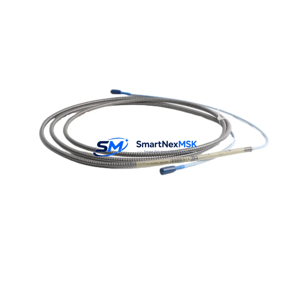
The Bently Nevada 330130-030-01-CN is a 3-metre proximity probe extension cable engineered for the 3300 XL Series vibration monitoring system — one of the most widely deployed machinery protection platforms in rotating equipment facilities worldwide. When a plant experiences unexpected vibration monitor faults, a degraded or open-circuit extension cable is among the first components that maintenance engineers must isolate and replace. Sourcing a verified original spare with full traceability is critical to restoring protection coverage and minimising unplanned downtime on turbines, compressors, pumps, and gearboxes.
This cable serves as the signal conduit between the proximity probe tip (typically a 330101 or 330103 series probe) and the Bently Nevada 3300 XL proximitor/driver module mounted in the control cabinet. Any degradation in cable shielding, connector integrity, or impedance matching directly affects the gap voltage output and vibration amplitude readings fed into the 3500 Series rack or legacy 3300 Series monitors. Maintenance teams performing planned outage inspections or responding to a high-vibration trip should treat the extension cable as a consumable-grade spare that warrants proactive replacement on a defined interval.
Spare Maintenance Table
| Part Number | 330130-030-01-CN |
| Brand | Bently Nevada |
| Series | 3300 XL Proximity System |
| Type | Proximity Probe Extension Cable |
| Cable Length | 3.0 m (9.84 ft) |
| Connector Type | Coaxial, armoured, field-replaceable |
| Compatible Probes | 330101, 330103, 330104 Series Proximity Probes |
| Compatible Drivers | 330180, 330185 Proximitor Sensors; 3300 XL 8mm Driver |
| System Compatibility | 3300 XL, 3500 Series Machinery Protection Racks |
| Operating Temperature | -40 °C to +121 °C |
| Origin | USA |
| Condition | Original, New-in-Box / Tested Surplus |
| Application Environment | Turbines, Compressors, Pumps, Gearboxes, Rotating Machinery |
| Maintenance Recommendation | Inspect connectors and shielding at every planned outage; replace if gap voltage drift exceeds ±0.5 V from baseline |
| Warranty | 12 Months from date of shipment |
| Pre-shipment Testing | Continuity, insulation resistance, and impedance verified before dispatch |
Maintenance Planning for Continuous Operation
A structured spare parts strategy for the 3300 XL proximity system extends well beyond the extension cable itself. When replacing the 330130-030-01-CN, maintenance engineers should simultaneously audit the complete signal chain to prevent repeat failures and ensure the protection system returns to full specification.
Begin at the probe tip: verify that the 330101-00-08-10-02-00 or equivalent 8mm proximity probe shows correct gap voltage (typically –10 to –18 VDC) after cable swap. If gap voltage remains out of range, the probe itself may require replacement. Moving toward the cabinet, inspect the 330180-X1-05 proximitor sensor for output linearity and confirm that the coaxial connector seating is secure — a loose proximitor connection is a common source of intermittent high-vibration alarms that are misdiagnosed as mechanical faults.
Inside the control cabinet, check the 3500/42M or 3500/40M proximity monitor card for any latched fault LEDs and verify that the OK relay output is healthy. If the rack uses a 3500/20 rack interface module, confirm that the system power supply — typically a 3500/15 or equivalent 24 VDC power module — is delivering stable voltage within tolerance, as supply ripple can induce false vibration readings. Fuse integrity on the power distribution rail should be confirmed with a calibrated multimeter before re-energising the loop.
For facilities running hybrid architectures, where 3300 XL field devices feed into a 3500 Series rack via signal conditioning, also inspect the 3500/05 system rack backplane connectors for corrosion or fretting. Terminal blocks and cable glands at the junction box should be re-torqued to manufacturer specification. Where signal runs exceed 9 metres, a signal isolator or barrier in the loop should be tested for correct pass-through gain. Finally, if the plant uses a System 1 or System 1 Evolution condition monitoring software platform, confirm that the channel configuration reflects the new cable’s exact length so that the software’s gap voltage alarm setpoints remain valid.
Procurement engineers should maintain a minimum of two 330130-030-01-CN cables per critical machine train in the on-site spare parts inventory. Given the long lead times historically associated with Bently Nevada OEM channels, sourcing verified original spares from authorised distributors with immediate stock availability is the most effective strategy for protecting uptime commitments.
Site Replacement Workflow
Step 1 — Isolate and document: Before disconnecting the existing cable, record the current gap voltage reading from the monitor display or System 1 software. This baseline is essential for post-replacement verification. Tag the machine and notify the control room that the proximity channel will be temporarily out of service.
Step 2 — Disconnect and inspect: Remove the extension cable at both the probe end and the proximitor end. Inspect the probe tip for physical damage, contamination, or thread wear. Clean the probe face with isopropyl alcohol if required. Inspect the proximitor connector for bent pins or moisture ingress.
Step 3 — Install the 330130-030-01-CN: Route the new cable following the original cable path to avoid mechanical stress or proximity to high-voltage conductors. Secure with cable ties at the same intervals as the original installation. Hand-tighten coaxial connectors to the specified torque — over-tightening damages the centre pin.
Step 4 — Verify gap voltage: With the machine at rest, confirm that the gap voltage falls within the system’s calibrated range (typically –10.0 to –18.0 VDC for 8mm probes). Adjust the probe gap if necessary using a non-ferrous feeler gauge. Document the final gap voltage in the maintenance record.
Step 5 — Return to service: Clear the channel fault in the monitor rack, confirm the OK relay has re-energised, and notify the control room. Log the replacement in the CMMS with the new cable’s serial number and installation date to support the 12-month warranty tracking.
This workflow is compatible with both direct replacement of legacy 3300 Series installations and integration into current 3500 Series racks, ensuring system continuity without requiring re-commissioning of the full protection loop.
Spare Parts Support FAQ
Q1: Is the 330130-030-01-CN compatible with both the 3300 XL and 3500 Series systems?
Yes. The 330130-030-01-CN is designed for the 3300 XL proximity system and is fully compatible when used with 3300 XL probes and proximitor sensors feeding into 3500 Series monitor racks. Always confirm the total system cable length (probe + extension) matches the proximitor’s calibrated range specification before installation.
Q2: What pre-shipment testing is performed on this spare?
Every unit is tested for electrical continuity, insulation resistance, and coaxial impedance before dispatch. A test report is available upon request. Units are shipped in anti-static packaging with connector caps to protect the mating surfaces during transit.
Q3: How should this cable be stored in a spare parts inventory?
Store in a clean, dry environment at 15–35 °C, away from direct sunlight and electromagnetic sources. Keep connectors capped and coiled loosely — do not bend the cable tighter than a 50mm radius. Inspect stored cables annually for connector oxidation and sheath integrity. Rotate stock on a first-in, first-out basis.
Q4: What is covered under the 12-month warranty?
The 12-month warranty covers manufacturing defects, connector failure under normal operating conditions, and shielding integrity. It does not cover damage resulting from incorrect installation, mechanical abuse, or operation outside the specified temperature range. Warranty claims are supported with a replacement unit dispatched within 5 business days of fault confirmation.
© 2026 SMARTNEXMSK. All rights reserved.
Original Source: https://smartnexmsk.com
Contact: sales@smartnexmsk.com | +86 18259474341


