Bently Nevada 330130-040-12-00 Retrofit-Ready Proximity Transducer for 3300 XL Control Systems
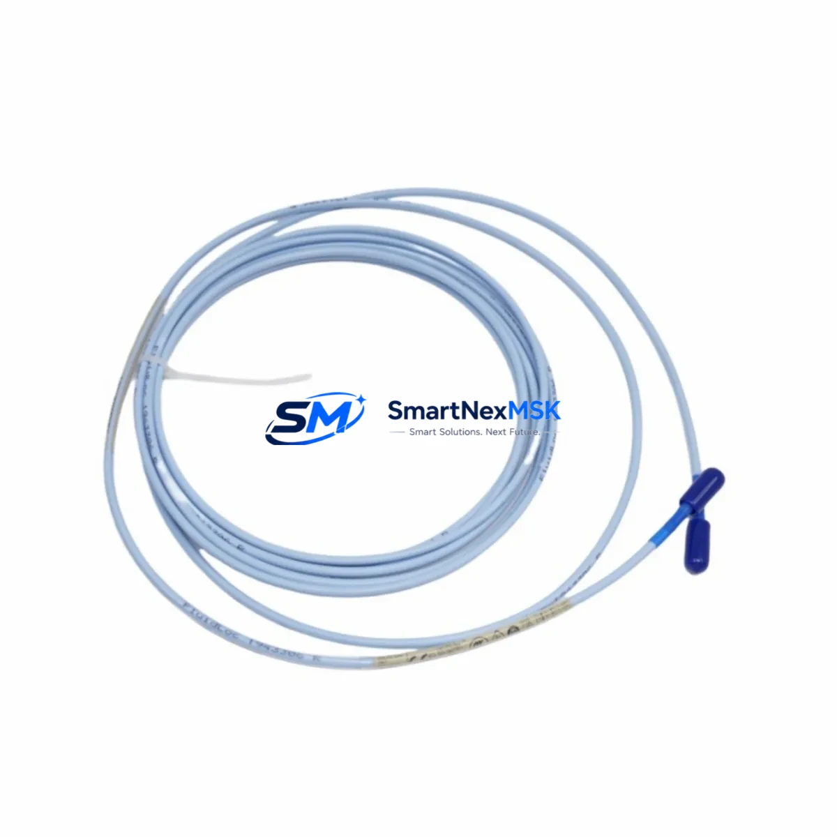
The Bently Nevada 330130-040-12-00 is an 8mm eddy-current proximity transducer engineered for seamless integration into existing 3300 XL Series vibration monitoring systems. Whether you are replacing a failed unit on a critical rotating machine, upgrading an aging condition monitoring network, or restoring a legacy protection system after an unplanned shutdown, this transducer delivers the dimensional accuracy, signal linearity, and connector compatibility required for a direct, no-rework installation.
Industrial facilities operating gas turbines, steam turbines, compressors, pumps, and gearboxes that were originally commissioned with Bently Nevada 3300 XL monitors rely on this transducer as the primary sensing element for radial shaft vibration, axial position, and differential expansion measurement. The 330130-040-12-00 integrates directly with the 3300 XL 8mm Extension Cable (typically the 330130-080-00-00 or 330130-085-00-00 cable assemblies) and the matched 3300 XL Proximitor Sensor (such as the 330180-X1-05 or 330180-X1-CN series) to form a complete eddy-current measurement chain. Replacing only the transducer while retaining the original extension cable and Proximitor preserves the system calibration gap and eliminates the need for full-chain recalibration in most installations.
Upgrade Compatibility Table
| Parameter | Detail |
|---|---|
| SKU / Part Number | 330130-040-12-00 |
| Probe Diameter | 8 mm |
| Cable Length (Integral) | 1.0 m (40 inches) |
| Connector Type | MIL-C-5015 style, compatible with 3300 XL extension cables |
| Compatible Monitor Series | Bently Nevada 3300 XL, 3500 Series (with adapter), 3300/20 legacy |
| Compatible Proximitor | 330180-X1-05, 330180-X1-CN, 330180-51-05 |
| Compatible Extension Cables | 330130-080-00-00, 330130-085-00-00 |
| Installation Requirement | Direct drop-in; verify gap voltage (–10 VDC nominal at 1.0 mm) |
| Communication / Signal | Analog voltage output (–24 VDC supply, 200 mV/mil sensitivity) |
| Replacement Compatibility | Direct replacement for 330130-040-12-00; cross-compatible with 330130-040-00-00 (verify cable length) |
| Retrofit Recommendation | Replace transducer only; retain original Proximitor and extension cable to preserve calibration |
| Debugging Focus | Gap voltage verification, OK relay status, signal noise floor check |
| Warranty | 12 Months from date of shipment |
Retrofit Planning for Existing Automation Systems
A successful retrofit of the 330130-040-12-00 begins well before the maintenance window opens. Engineers should pull the existing loop drawing to confirm the transducer mounting thread (M10 × 1.0), the installed gap distance, and the routing path of the extension cable. In most 3300 XL installations, the 3300 XL Proximitor Sensor is mounted in a junction box or directly on the machinery guard, and the signal is routed back to a 3300/16-15-01-01-00-00-00 monitor card seated in a 3500/01 Rack Power Supply chassis or a dedicated 3300 XL rack. Confirming the rack slot address and the channel configuration in the System 1 software (or the legacy 3300 XL configuration tool) before the outage prevents address conflicts during recommissioning.
For facilities migrating from a 3300/20 or earlier 3300 series platform toward the 3300 XL or 3500 architecture, the 330130-040-12-00 transducer is fully compatible with the newer Proximitor electronics, making it a practical first step in a phased upgrade. The second phase typically involves replacing the 3300/20 Monitor with a 3500/42M Proximitor / Seismic Monitor and updating the I/O wiring to the new terminal block pinout. During this phase, engineers must also verify that the 3500/20 Rack Interface Module is configured for the correct communication protocol — whether Modbus RTU, Modbus TCP, or the proprietary System 1 protocol — to ensure the DCS or SCADA historian continues to receive vibration data without interruption.
Power supply capacity is a critical checkpoint. The 3300 XL Proximitor draws approximately 25 mA per channel from the –24 VDC supply rail. When adding channels or replacing multiple transducers simultaneously, verify that the 3500/15 Power Supply or the existing rack power module has sufficient headroom. Overloaded supply rails are a common cause of intermittent OK relay dropouts that are misdiagnosed as transducer failures. Similarly, when upgrading the I/O count by adding a 3500/40M Proximitor / Seismic Monitor alongside the existing cards, the backplane current budget must be recalculated.
Terminal wiring adaptation is straightforward for direct replacements: the transducer connector mates with the existing extension cable without modification. However, if the extension cable is also being replaced — for example, upgrading from a 5-metre to an 8-metre run using the 330130-085-00-00 — the total system scale factor must be re-entered in the monitor configuration to maintain accurate engineering-unit readout in the HMI. Operators should also update the System 1 Evolution or System 1 Condition Monitoring database to reflect the new cable serial number and calibration date, ensuring traceability for the next planned inspection.
Downtime Control During System Migration
Minimising unplanned downtime during a transducer replacement requires a structured pre-outage checklist and a clear rollback plan. Before isolating the loop, capture a screenshot or historian export of the current vibration trend, gap voltage, and OK relay status from the System 1 workstation or the DCS faceplate. This baseline record allows the commissioning engineer to confirm that the replacement 330130-040-12-00 is performing within the same envelope as the original unit before the machine is returned to service.
During the physical swap, the monitor channel should be placed in bypass mode (if the 3500 or 3300 XL firmware supports it) to prevent a spurious trip signal from reaching the ESD system while the transducer is disconnected. After installing the new transducer and reconnecting the extension cable, measure the gap voltage at the Proximitor OK terminals before re-enabling the channel. A reading of –10 VDC ± 1 VDC at the nominal 1.0 mm air gap confirms correct installation. If the gap voltage is outside this range, adjust the transducer depth in the mounting bracket in 0.25 mm increments until the target is achieved.
Once the gap is set, re-enable the monitor channel and observe the vibration reading for a minimum of five minutes at operating speed before releasing the bypass. Compare the live reading against the pre-outage baseline. A deviation of less than 5% confirms that the original program logic, alarm setpoints, and HMI display values remain valid and do not require adjustment. This approach protects the existing control logic, preserves the historian continuity, and allows the maintenance team to close the work order with full confidence that the system is operating correctly.
Retrofit Support FAQ
Q1: Is the 330130-040-12-00 a direct drop-in replacement for the original unit?
Yes. The 330130-040-12-00 shares the same M10 × 1.0 mounting thread, 8 mm probe diameter, MIL-style connector, and 200 mV/mil sensitivity as the original factory-installed unit. No mechanical modification or recalibration of the Proximitor is required when replacing like-for-like. Verify the gap voltage after installation to confirm correct positioning.
Q2: Can this transducer be used with a Bently Nevada 3500 Series monitor?
Yes, with the appropriate Proximitor. The 330130-040-12-00 is compatible with 3500 Series systems when paired with a 3500-series-compatible Proximitor such as the 330180-X1-05. Confirm the monitor card firmware version supports 8 mm transducer input and that the scale factor is set to 200 mV/mil in the rack configuration software.
Q3: What wiring checks are required before powering up the replacement transducer?
Verify continuity of the extension cable shield and centre conductor, confirm the –24 VDC supply voltage at the Proximitor input terminals, and check that the terminal block screws are torqued to the manufacturer specification (typically 0.5–0.6 N·m). Inspect the connector O-ring for damage before mating, particularly in outdoor or high-humidity installations.
Q4: What does the 12-month warranty cover?
All units are functionally tested prior to shipment. The 12-month warranty covers manufacturing defects and electrical performance failures under normal operating conditions. Each shipment includes a test report. Warranty claims are processed within 5 business days of receipt of the returned unit. Contact sales@smartnexmsk.com for RMA authorisation.
© 2026 SMARTNEXMSK. All rights reserved.
Original Source: https://smartnexmsk.com
Contact: sales@smartnexmsk.com | +86 18259474341


