Bently Nevada 330130-075-10-05 Spare 3300 XL Automation
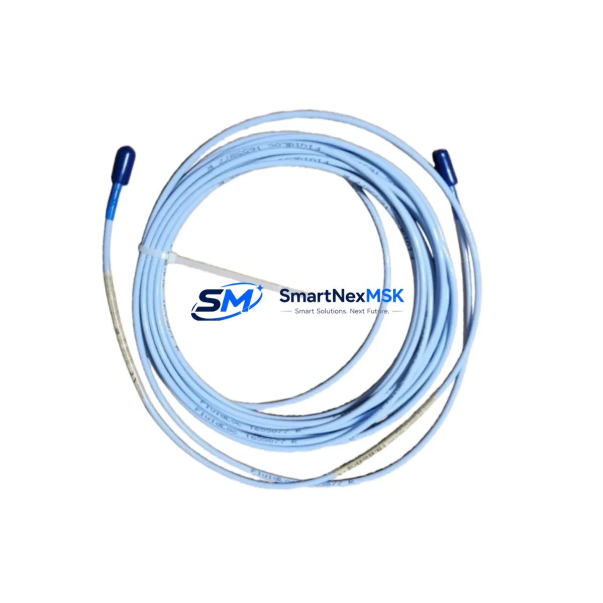
The Bently Nevada 330130-075-10-05 is an original proximity extension cable engineered for the 3300 XL series continuous vibration monitoring system. With a 7.5-metre (25-foot) cable length and precision-matched impedance characteristics, this extension cable forms the critical signal path between the 3300 XL proximitor/sensor and the monitoring rack — making it a front-line spare for any rotating machinery protection programme. Unplanned downtime caused by a degraded or failed extension cable can halt turbines, compressors, pumps, and gearboxes within minutes. Holding a verified replacement in your spare parts inventory is the single most cost-effective insurance against that risk.
This unit ships fully tested, individually packaged, and covered by a 12-month warranty against manufacturing defects. Each cable is inspected for connector integrity, shield continuity, and impedance conformance before dispatch, ensuring it is ready for immediate field installation without additional bench testing.
Spare Maintenance Table
| Parameter | Specification |
|---|---|
| Part Number | 330130-075-10-05 |
| Series | Bently Nevada 3300 XL |
| Type | Proximity Extension Cable |
| Cable Length | 7.5 m (25 ft) |
| Connector Type | MIL-C-5015 style, coaxial, gold-plated |
| Impedance | Matched to 3300 XL proximitor system |
| Operating Temperature | -40 °C to +85 °C |
| Shield | Double-braided, 95% coverage |
| Compatibility | 3300 XL 8mm Proximitor Sensor, 3300 XL 11mm Proximitor Sensor, 3300 XL 14mm Proximitor Sensor |
| Application | Radial vibration, axial position, differential expansion monitoring |
| Installation Environment | Industrial — turbine halls, compressor skids, pump stations |
| Maintenance Recommendation | Inspect connectors and cable jacket every 12 months; replace at first sign of insulation cracking or connector corrosion |
| Warranty | 12 Months |
| Condition | Original, new stock |
Maintenance Planning for Continuous Operation
When a 330130-075-10-05 extension cable is flagged for replacement during a planned outage or emergency callout, experienced maintenance engineers treat the event as a trigger for a broader inspection of the entire vibration monitoring loop. The extension cable does not operate in isolation — it is one link in a chain that includes the proximitor/sensor (such as the 330780-50-00 or 330730-040-00-00 eddy-current probe), the 3300 XL proximitor module mounted in the field junction box, and the rack-mounted monitor card in the control cabinet.
Begin by verifying the DC gap voltage at the proximitor output with a calibrated multimeter; a reading outside the –10 VDC to –18 VDC window indicates either a probe gap error or a cable fault. While the cabinet is open, inspect the 3300 XL power supply module — typically a 125 VDC or 24 VDC unit — for output ripple and terminal tightness. A marginal power supply will cause intermittent channel trips that mimic cable faults and are frequently misdiagnosed in the field.
Check the terminal blocks and field wiring at the junction box for moisture ingress, corrosion, or loose ferrules. Vibration environments accelerate terminal fatigue, and a loose shield ground on the extension cable can introduce 50/60 Hz noise that corrupts the vibration waveform. If the plant uses a Bently Nevada 3500 series rack alongside legacy 3300 XL hardware, confirm that the cable impedance and length combination is within the proximitor’s calibrated range — mismatched cables are a common source of false high-vibration alarms.
For facilities running long-term asset life extension programmes on older turbomachinery, it is prudent to stock at least one spare 330130-075-10-05 alongside complementary items such as the 330130-045-10-05 (4.5 m variant) for shorter runs, the 330180-X-05 armoured extension cable for high-vibration zones, and the 330105-02-12-10-02-00 proximity probe for complete loop replacement. Relay output modules, I/O terminal boards, and signal conditioners in the same rack bay should also be included in the periodic inspection checklist to avoid cascading failures after a cable swap.
Where the plant DCS or safety instrumented system (SIS) receives 4–20 mA or discrete trip signals from the 3300 XL monitor, verify signal integrity at the marshalling cabinet after cable replacement. A signal isolator or barrier in the loop — such as a Pepperl+Fuchs or MTL unit — should be checked for drift if the channel has been in alarm. HMI trend screens should be reviewed for baseline shift before the machine is returned to service.
Site Replacement Workflow
Step 1 — Isolate and document. Before disconnecting the existing 330130-075-10-05, record the DC gap voltage, vibration amplitude, and any active alarms from the 3300 XL monitor display or DCS historian. This baseline is essential for post-replacement verification.
Step 2 — Disconnect safely. De-energise the proximitor supply at the field junction box. Disconnect the extension cable at both the probe end and the proximitor end, noting the connector orientation and any cable routing clamps.
Step 3 — Inspect mating connectors. Clean the probe and proximitor connector threads with isopropyl alcohol. Inspect the gold-plated centre pin for damage or contamination. Replace the probe or proximitor if connector damage is found — installing a new cable onto a damaged mating connector will shorten the replacement cable’s service life.
Step 4 — Install the replacement. Route the new 330130-075-10-05 following the original cable path, maintaining minimum bend radius and avoiding contact with hot surfaces or high-voltage conductors. Torque connectors to the manufacturer’s specification.
Step 5 — Re-energise and verify. Restore power and confirm DC gap voltage is within the –10 VDC to –18 VDC calibrated range. Check the 3300 XL monitor for channel OK status and confirm vibration readings are consistent with pre-outage baseline. Clear any latched alarms only after verification is complete.
Step 6 — Update maintenance records. Log the replacement date, cable serial number, and post-installation gap voltage in the plant CMMS. Schedule the next inspection interval — typically 12 months or at the next planned outage, whichever comes first.
Spare Parts Support FAQ
Q1: Is the 330130-075-10-05 compatible with both 8 mm and 11 mm 3300 XL proximitor sensors?
Yes. The 330130-075-10-05 extension cable is designed for use across the 3300 XL proximitor sensor family, including 8 mm, 11 mm, and 14 mm variants, provided the total system cable length (probe cable + extension cable) remains within the proximitor’s calibrated range. Always verify the combined length against the proximitor datasheet before installation.
Q2: How do you verify a replacement cable before installation on a live machine?
Each unit shipped by SMARTNEXMSK has been bench-tested for shield continuity, centre-conductor resistance, and connector integrity. On-site, use a calibrated multimeter to confirm shield-to-centre-conductor isolation (>1 MΩ) and centre-conductor continuity before connecting to the proximitor. This two-minute check eliminates the risk of installing a transit-damaged cable.
Q3: What is the recommended spare parts stocking strategy for a plant with 20+ 3300 XL channels?
Industry best practice for critical rotating machinery is to hold a minimum of 10% of installed channel count as on-site spares for high-wear consumables such as extension cables and probes. For a 20-channel installation, two 330130-075-10-05 cables and two matched probes provide adequate coverage for most unplanned failure scenarios without excessive inventory carrying cost.
Q4: What does the 12-month warranty cover, and how is a warranty claim processed?
The 12-month warranty covers manufacturing defects in materials and workmanship from the date of shipment. It does not cover damage resulting from incorrect installation, mechanical abuse, or use outside the specified environmental ratings. To initiate a warranty claim, contact sales@smartnexmsk.com with the order number, part number, and a description of the fault. Replacement units are dispatched within 3 business days of claim approval.
© 2026 SMARTNEXMSK. All rights reserved.
Original Source: https://smartnexmsk.com
Contact: sales@smartnexmsk.com | +86 18259474341


